They do sound pretty good.Those are some pretty interesting speakers!
looks like fun.
Glad the amp is working.
If a previous repair was done Q209 or Q222 current limit /VI limiters could have been damaged from a output
failure.
But if the amp is passing signal then they would likely be ok
if shorted or failed closed they would clamp the signal.
Q213 is obviously ok since the amp is working.
It just had no current source since it wasn't connected and now fixed
Be interesting to hear those speakers
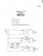
See the attached pic of their schematic.
Attachments
On a seemingly unrelated problem R201 the 1K resistor to the base of Q211 was 2K. Changed it....it was probably on its way to going totally open.
Q213 is obviously ok since the amp is working.
I did change it earlier in my repair quest, because of the rounded knee. It would be interesting to know if the original was causing a problem.
In my quest and because I had replacement transistors I also replaced the differential pair Q211 and Q212 along with Q201. I had removed them to test and I had replacements so I used them.
Also replaced Q202 and Q214 since I also removed to test and I had replacements. As it turned out Q202's collector wasn't connected.
I learned quite a bit on this repair. I did alot of head scratching because I did not expect the transistor collector not to be connected to the circuitry. The voltages and amp behavior had me going in circles.
These forums are fantastic!!
It is so beneficial to be able to have another set of eyes and brains on a problem.
Once Again a big thank you to the forum and more specifically Mooly and White Dragon!!!!
Last edited:
Yup. Appears to be working!
Still gonna put it thru its paces....Test output power @ 200W per side.
Harmonic Distortion and Freq, Response, but I think we'll be good to go!!
Still gonna put it thru its paces....Test output power @ 200W per side.
Harmonic Distortion and Freq, Response, but I think we'll be good to go!!
Somebody had tried to repair earlier and the trace around the collector of Q202 was damaged. There was no connection between the collector and the cct. brd. Q202 collector went to nowhere
I'm very happy to report that the amp is working perfectly after putting it thru the paces.
Over 300W per side individually before clipping. I didn't test both channels simultaneously since it's rated at 200W per side.
Both channels are well within spec for harmonic distortion. Less than .1%. Measured .07%
Both channels within 1 dB on the frequency response 20Hz to 20Khz @2 watts
3.9VAC to 4.0VAC across the dummy load of 8 ohms.
I'm very happy with my purchase of this 45 year old amp.
Replaced all the electrolytic caps except the two main ones as they still tested ok.
The only caps that I replaced that tested poorly were the 10 ufd 150V ones on the input of the rails on the output boards. C206 and C219.
Amazing equipment designed back in the day.
They do sound pretty good.
See the attached pic of their schematic.
Pleased to hear you found the fault 🙂
Thanx for your help!!!
You are very knowledgeable!!
Hi gabby. I know this is a 3 year old thread but I am working on one of these amps. Sadly I lost the install manual with clear schematics. The schemas I find online are of rather poor quality and many of the values particularly the voltages are very hard to read. do you know where I can get a better quality schematic. The problem I have is very similar to what you describe here only it is not a bad solder joint.I have a Heathkit Power Amp AA-1640 that has an issue on the left channel that I believe I found. Thinking about replacing the 2N4889's with MPS A92.
The seem to be close enough. I also have some 2N5401 that would/could work.
Any comments or suggestions. They are Q201, Q211 and Q212.
Q213 I believe is the culprit (See Huntron Pics), but while I'm in there I want to change the transistors that may have been stressed as a result.
Q213 was a MPS A42.
The faulty Q213 has a rounded elbow on the defective transistor. It is the emitter collector junction. The nice square elbow is a known good transistor. These pics are on my Huntron Tracker 2000.
Transistor tested good on my Heathkit IT-121.
The Huntron rarely misses.
- Home
- Amplifiers
- Solid State
- 2N4889 Substitute