I have a Heathkit Power Amp AA-1640 that has an issue on the left channel that I believe I found. Thinking about replacing the 2N4889's with MPS A92.
The seem to be close enough. I also have some 2N5401 that would/could work.
Any comments or suggestions. They are Q201, Q211 and Q212.
Q213 I believe is the culprit (See Huntron Pics), but while I'm in there I want to change the transistors that may have been stressed as a result.
Q213 was a MPS A42.
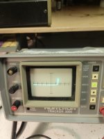
The faulty Q213 has a rounded elbow on the defective transistor. It is the emitter collector junction. The nice square elbow is a known good transistor. These pics are on my Huntron Tracker 2000.
Transistor tested good on my Heathkit IT-121.
The Huntron rarely misses.
The seem to be close enough. I also have some 2N5401 that would/could work.
Any comments or suggestions. They are Q201, Q211 and Q212.
Q213 I believe is the culprit (See Huntron Pics), but while I'm in there I want to change the transistors that may have been stressed as a result.
Q213 was a MPS A42.
The faulty Q213 has a rounded elbow on the defective transistor. It is the emitter collector junction. The nice square elbow is a known good transistor. These pics are on my Huntron Tracker 2000.
Transistor tested good on my Heathkit IT-121.
The Huntron rarely misses.
Attachments
Last edited:
The 2N5401's should fine for where you suggest.
Q213 and 214 need to be able to withstand the full total rail voltage plus a decent margin and so 250 volt or higher rated devices are needed.
Q213 and 214 need to be able to withstand the full total rail voltage plus a decent margin and so 250 volt or higher rated devices are needed.
MJE 350
Glad you mentioned Q214. It's a MJE 350 and though it tests ok I decided to also change it cause I had one, and it's also in the vicinity. ( I initially didn't test cause I assumed it was probably ok)( I should know better than to assume though in this case I think I would have been ok)
I ended up going with the MPS A92's for the Q201, Q211, and Q212 cause their gain was closer to the 2N4889. (Measured) Their Voltage is higher than the 2N4889 so good on that front also.
Just about ready to apply power????
Thanks for replying!
Last edited:
Applied power...no smoke but still has the same problem.
Time to get serious about troubleshooting.
Scope and DVM work ahead.
The right channel is good to I'll have something to compare.
Time to get serious about troubleshooting.
Scope and DVM work ahead.
The right channel is good to I'll have something to compare.
Heathkit AA-1640 Wows
On the good Ch. RT.I have a good sine wave at the Emitter of Q211
On the bad Ch. LT I have no sine wave on the Emitter of Q211.
I'm applying a 1KHZ signal to the normal input.
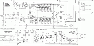
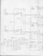
From the schematic I should have something on the collectors but no sine wave on either.
Q211 has been changed with a MPS A92
Voltages are similar on the EBC for both.
RT Q211 E .63V B .08V C -92V
Lt Q211 E.46V B 0V C-93 V
On the good Ch. RT.I have a good sine wave at the Emitter of Q211
On the bad Ch. LT I have no sine wave on the Emitter of Q211.
I'm applying a 1KHZ signal to the normal input.
From the schematic I should have something on the collectors but no sine wave on either.
Q211 has been changed with a MPS A92
Voltages are similar on the EBC for both.
RT Q211 E .63V B .08V C -92V
Lt Q211 E.46V B 0V C-93 V
Last edited:
The signal on the collector will be very small indeed and could resemble a triangular wave... all normal if it does.
Are the main DC conditions correct?
1/ Output offset at the output < -/+ 100 millivolts.
2/ Is the output stage drawing the correct quiescent current? Check by measuring volt drop across any of the 1 ohm 10 watt resistors.
Does the map (edit... LOL, amp) have a hidden history?
Is the link shown on the diagram fitted that couples the input to Q211.
The signal on the collector will be very small indeed and could resemble a triangular wave... all normal if it does.
Very Astute...that is exactly what I see.
Are the main DC conditions correct?
Yes the mains are +/_ 93 volts..The right channel seems to be working perfectly
1/ Output offset at the output < -/+ 100 millivolts.
2/ Is the output stage drawing the correct quiescent current? Check by measuring volt drop across any of the 1 ohm 10 watt resistors.
No. On the working channel I have about .5V on the B-E junction of the output transistors. On the non working channel it is 0VDC.
I have 1.7V on the B of Q203 working channel.
-.2v on the B of Q203 non working channel.
Does the map (edit... LOL, amp) have a hidden history?
Not sure about the history. I have this amp personally in my collection and then this same amp came up for sale locally so I purchased it. ( It was supposed to be working??) (Famous last words) (Maybe a spare)
Though I did find a repair invoice in the manual where the left channel was repaired about 25 years ago??? Maybe repaired??
Is the link shown on the diagram fitted that couples the input to Q211.
Not sure what you mean here though the signal is going thru the input brd to the main brd, and I do see a good sine wave at the B of Q211 on both channels.
I suspect Q202 might be faulty. On the good channel I have 4.0V on the Collector as per schematic.
On the bad channel I have 93V on the collector.
I will pull it and test.
I forgot to test earlier as per your suggestion!!!
On the bad channel I have 93V on the collector.
I will pull it and test.
I forgot to test earlier as per your suggestion!!!
If you suspect Q202 then first measure the voltage across that 27 ohm in the emitter and also measure the voltage across C204 (the cap across the diode chain).
You should see around 0.65 volts (about) across the resistor and about 3 volts across the diode chain.
You should see around 0.65 volts (about) across the resistor and about 3 volts across the diode chain.
I suspect Q202 might be faulty. On the good channel I have 4.0V on the Collector as per schematic.
On the bad channel I have 93V on the collector.
I will pull it and test.
I forgot to test earlier as per your suggestion!!!
Posting together.
OK, that shows a major issue. If you have +93v on the collector then that voltage should carry through to the output. Obviously not desirable 😉 but that should happen as each B-E junction in the Q203, Q204 and Q205 chain conduct.
If that is not happening then if you place your black meter lead on the main output line (which is fuse F303) and measure back via all the base and emitter nodes then you should find the problem area.
Are you sure the 0.22 ohms are OK?
Q201 and Q202 would be suspect.
From the other posted voltages it would seem as if the current sources are not working.
In this cause if you are seeing full rail voltage on Q202 it seems to be failed shorted.
Even if failed shorted. The 27 ohm resistor should drop a little bit of voltage. But voltage seems to be at full rail.
So you should of course check Q202.
Then any associated resistor or diode in the current source circuit. Which may have been cooked.
Also assume Q202 failed for a reason, so the thermal tracking diodes and Vas is also suspect.
I think I found the problem!!!
I pulled Q202 to test and it did test ok. Replaced it anyway cause I had the MJE350 in stock.
Pretty sure the transistor wasn't at fault, but the soldering on the collector was suspect.
Their wasn't much left of the copper trace for the collector...most likely was removed when someone tried to repair way back whenever.
I think the collector was not connected to the copper trace and was just open.
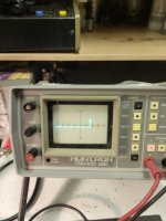
Having said that there is a new transistor in Q202 but the old one does look good on two different test sets. Heathkit IT-121 and Hunrton Tracker 2000.
I think I'll hook it up to my curve tracer to see how it looks there to satisify my curiosity.
I pulled Q202 to test and it did test ok. Replaced it anyway cause I had the MJE350 in stock.
Pretty sure the transistor wasn't at fault, but the soldering on the collector was suspect.
Their wasn't much left of the copper trace for the collector...most likely was removed when someone tried to repair way back whenever.
I think the collector was not connected to the copper trace and was just open.
Having said that there is a new transistor in Q202 but the old one does look good on two different test sets. Heathkit IT-121 and Hunrton Tracker 2000.
I think I'll hook it up to my curve tracer to see how it looks there to satisify my curiosity.
I was going to mention by any rare chance Q202 tested ok.
The only way to get positive voltage on the collector would be
1) collector isnt connected to the rest of the circuit.
2) Q213 ( vas transistor) would have to fail open not shorted.
3) Thermal tracking diodes would have to fail open not shorted
otherwise if the vas or diodes shorted closed , then would more likely see a negative voltage on Q202 collector.
So that sounds like good news, that it was just a poor collector connection.
Someone has been in there before.
So it seems like a previous repair attempt.
Being a pa type amplifier assume the original possible fault was a failed/shorted output device from a shorted output.
If Q202 was originally replaced meaning excessive current might have killed it.
Could assume the output device failure was on the negative rail, not the positive.
Or at least more likely the current source would have seen more excessive current if Q217 - 214 had failed closed.
Last edited:
Both channels sound good thru a speaker and look good on my oscilloscope.
Now I have two Heathkit AA-1640 Power Amps.
I built mine way back when I was 18...some 45 years ago along with the matching Pre Amp and speakers.
I now have a spare or probably just put it up for sale at some point.
I need to replace a couple more electrolytic caps on the good channel and do a few more tests on both. (Harmonic Distortion and Freq. Response)
A big thank you to Mooly and White Dragon for your assistance.
White Dragon...Very good observation about the collector of Q202 not being connected!!
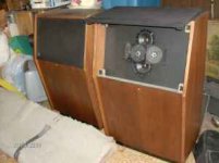
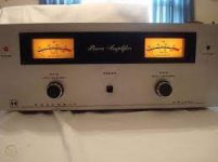
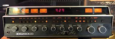
My Heathkit System
Here's a few pics of the Heathkit Stereo setup I built some 45 years ago as a teenager. 200W per side. Drove the neighbors crazy when I was living at home.
Still have it today and still sounds great playing my vinyl. Very little maintenance required....electrolytic caps fairly recently.
Here's a few pics of the Heathkit Stereo setup I built some 45 years ago as a teenager. 200W per side. Drove the neighbors crazy when I was living at home.
Still have it today and still sounds great playing my vinyl. Very little maintenance required....electrolytic caps fairly recently.
Attachments
I was going to mention by any rare chance Q202 tested ok.
The only way to get positive voltage on the collector would be
1) collector isnt connected to the rest of the circuit.
2) Q213 ( vas transistor) would have to fail open not shorted.
3) Thermal tracking diodes would have to fail open not shorted
Q213 was suspect. If you scroll back to my original post I have a pic of a rounded knee on my Huntron Tracker. I also posted a pic of a good transistor with a nice sharp knee. My experience is those rounded elbow or knees indicate a faulty transistor.
otherwise if the vas or diodes shorted closed , then would more likely see a negative voltage on Q202 collector.
So that sounds like good news, that it was just a poor collector connection.
Someone has been in there before.
Definitely. I'm guessing that was the reason that it was for sale.
So it seems like a previous repair attempt.
Being a pa type amplifier assume the original possible fault was a failed/shorted output device from a shorted output.
If Q202 was originally replaced meaning excessive current might have killed it.
I think Q202 was original cause it had the Heathkit part number on it. It looks like it had been removed to test??
Then not a great job of replacement.
Could assume the output device failure was on the negative rail, not the positive.
Or at least more likely the current source would have seen more excessive current if Q217 - 214 had failed closed.
Thanx for your observations and assistance. You are very knowledgeable!
Those are some pretty interesting speakers!
looks like fun.
Glad the amp is working.
If a previous repair was done Q209 or Q222 current limit /VI limiters could have been damaged from a output
failure.
But if the amp is passing signal then they would likely be ok
if shorted or failed closed they would clamp the signal.
Q213 is obviously ok since the amp is working.
It just had no current source since it wasn't connected and now fixed
Be interesting to hear those speakers
Last edited:
- Home
- Amplifiers
- Solid State
- 2N4889 Substitute