
I think probably easiest to just say no, it will not work as an audio amplifier.
If you had sufficient base bias current (you probably don't with 680 ohm although it is supply dependent as well) then all that will happen is that each transistor will conduct heavily and get very hot.
There is no significant signal voltage (what you want) developed across the 0.33 ohm resistors.
If you had sufficient base bias current (you probably don't with 680 ohm although it is supply dependent as well) then all that will happen is that each transistor will conduct heavily and get very hot.
There is no significant signal voltage (what you want) developed across the 0.33 ohm resistors.
Thank you for the advise i thought it works as a ampI think probably easiest to just say no, it will not work as an audio amplifier.
If you had sufficient base bias current (you probably don't with 680 ohm although it is supply dependent as well) then all that will happen is that each transistor will conduct heavily and get very hot.
There is no significant signal voltage (what you want) developed across the 0.33 ohm resistors.
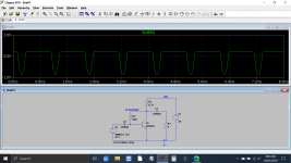
This is what would happen. The output voltage would be very distorted and of very limited level.
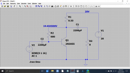
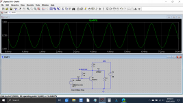
Assuming the gain of the transistors allowed this we could alter values and get something like this but it is still very poor and very inefficient. With a 20 volt supply we have 4 amps flowing and the transistor is dissipating nearly 50 watts. There is a bit more output voltage available now and the distortion is lower but still very poor.
Assuming the gain of the transistors allowed this we could alter values and get something like this but it is still very poor and very inefficient. With a 20 volt supply we have 4 amps flowing and the transistor is dissipating nearly 50 watts. There is a bit more output voltage available now and the distortion is lower but still very poor.
Attachments
You say so because Turkey is a hotbed of advanced Audio Design 🙄india style 🙂
150W RMS from a couple TIP142/147? 😛
You guys are really redefining Physics Laws 😀
404 Not Found
404 Not Found
DIY Audio Turkey, Darlington Amp

Darlington Çıkışlı Amplifikatör
Bir kaç aydır üzerinde çalıştığım projeyi nihayet tamamlayabildim.
Sizlere daha önce forumda En dandik ampli 🙂 başlığı altında tanıttığım bu uygulamanın şemasını ve PCB dizaynını yeniden çizip aynı zamanda göze de hitap eder bir hale getirmeye çalıştım.
Ayrıca drhardware'in de yardımıyla devre şemasında bir kaç ufak değişiklik yapıldı ve şu anki haline getirildi.
Devremiz şemadaki haliyle, girişinde sinyal yok ve çıkışında woofer bağlı iken (Girişe 10K lık potansiyometre koymayı ihmal etmeyin. Eğer koymayacaksanız -ki ben o şekilde kullandım- girişe paralel 4.7K lık bir direnç lehimleyiverin) 5 cm mesafeden sonra hiç bir ses duyamayacağınız kadar sessiz çalışıyor. Çıkışta tizler bağlı iken durum değişebilir şahsen denemedim şimdiden belirteyim.
Yukarıda anlattığım şekilde çalıştırdığınızda girişte sinyal yok iken çıkışta bir gürültü var ise ya bir yerde hata yaptınız veya kullandığınız malzemede sorun var demektir.
Beslemede, çıkışı 2X32 Volt olan 250W lık trafo kullanıldı. (Keşke trafoyu yaptırırken 2X35 Volt sardırsaydım.)
No.
2n3055 needs driver circuit and Vbe multiplier.
There are hundreds of better 2n3055 circuits out there from early years onwards.
However, i would recommend finding a more modern transistor.
The old 2n3055 struggles with gain and bandwidth.
2n3055 needs driver circuit and Vbe multiplier.
There are hundreds of better 2n3055 circuits out there from early years onwards.
However, i would recommend finding a more modern transistor.
The old 2n3055 struggles with gain and bandwidth.
Last edited:
You can always dig up the schematics for the B&O Beomaster 3000. It used the 2N3055 in its output stage.
Tom
Tom
No.
2n3055 needs driver circuit and Vbe multiplier.
The problem isn't actually the transistor ... it's the design the OP put up.
While it would do something, it would not work as an audio amplifier.
But that's not a bad thing... half of figuring out what works is understanding what doesn't.
Edison's famous quote comes to mind: "No sir I have not made a working light bulb. I have, however discovered dozens of ways not to make a working light bulb."
The gain on the 2n3055 is very low. So is Vce . So is bandwidth.
I have always said you only start to learn when something doesn't work.
I have always said you only start to learn when something doesn't work.
Yep. I'd guess that 90% of my troubleshooting skills came from that very situation.
The gain on the 2n3055 is very low. So is Vce . So is bandwidth.
I have always said you only start to learn when something doesn't work.
All the more reason to start with something expendable, like surplus 3055’s and low voltage power supplies. That circuit wouldn’t work with the latest and greatest $14 apiece 80 MHz fT sustained beta devices from Sanken. The values that Mooly suggested would get something working, albeit not well. You’d still be better off with cheap expendable parts for experiments like these. A lab power supply with a 3 or 4 amp fast acting current limit would also go a long way towards preventing instant charcoal.
Apex AX6 has the same # of transistors, 6, and works very well. Retro Amp 50W Single Supply - Page 22 - diyAudio
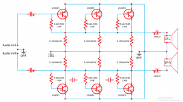
This needs the 0.33 resistors in the emitter leg instead of collector leg, to prevent thermal runaway. Need about a half amp of base drive to get 2.5 amps out, about max for a 2n3055. The 680 ohm base resistor won't allow that. AX6 uses 10 ohm OT base resistors. You'd have to have an audio amp as the source of the input to produce the half amp drive, too. Plus a 1000-2200 uf input cap. The driver transistors on the AX6 make the half amp drive, the vas transistor the voltage to drive them, and the input transistor gets drive current required to drive VAS down to what the earphone jack of a portable radio, CD player, mixer or preamp will provide. There is a diode stack between the drivers of AX6 to prevent the output transistors from switching on and off every time the input goes through zero - which sounds awful. Called "crossover distortion".
This needs the 0.33 resistors in the emitter leg instead of collector leg, to prevent thermal runaway. Need about a half amp of base drive to get 2.5 amps out, about max for a 2n3055. The 680 ohm base resistor won't allow that. AX6 uses 10 ohm OT base resistors. You'd have to have an audio amp as the source of the input to produce the half amp drive, too. Plus a 1000-2200 uf input cap. The driver transistors on the AX6 make the half amp drive, the vas transistor the voltage to drive them, and the input transistor gets drive current required to drive VAS down to what the earphone jack of a portable radio, CD player, mixer or preamp will provide. There is a diode stack between the drivers of AX6 to prevent the output transistors from switching on and off every time the input goes through zero - which sounds awful. Called "crossover distortion".
Last edited:
- Home
- Amplifiers
- Solid State
- 2n3055 Stereo Diagram??