OK I'm cheating😀
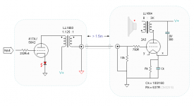
Everyone knows one 2A3 alone can never produce sufficient voltage gain for any source/speaker combo. So I'm cheating here with a very high gain pre amp - 417A/5842 with 1.125:1 OPT (reconfigured from 4.5:1 Lundahl LL1660). On paper, this pre (now driver) gives 135Vp-p (@ +/-2.1V input) and generous current drive for 2A3.
It's not a well-planned 'new' project. The major parts (irons and tubes) have been lying around for quite a long time, I just put them together now. And the aforementioned high gain pre amp is another major motivation. (I'd like to have as few stages as possible, now it's still two stages from DAC to speaker)
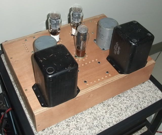
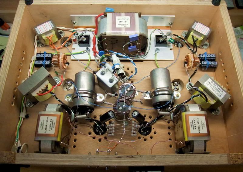
I'm lazy and hate metal work for amps, so I built it with (leftover) plywood. Other than those around tube sockets, I also drilled many holes around power and output transformers underneath for ventilation. These holes alone took me more than an hour. (However I was very happy it's not metal.)
The layout might be a little unusual. I put the tubes and OPTs at the rear for short signal paths. While the heaviest chokes and power transformer line up in the front makes it easier for me to lift/move. No looker, not to mention pretty, but I'm OK with that.
I own a 300B amp with a lot of irons which are in the rear half of the chasis (like most amps). With the load at the far side, it hurt my back several times. Ouch! 🙁
For a single stage triode, what can I do? It's all text book setup.
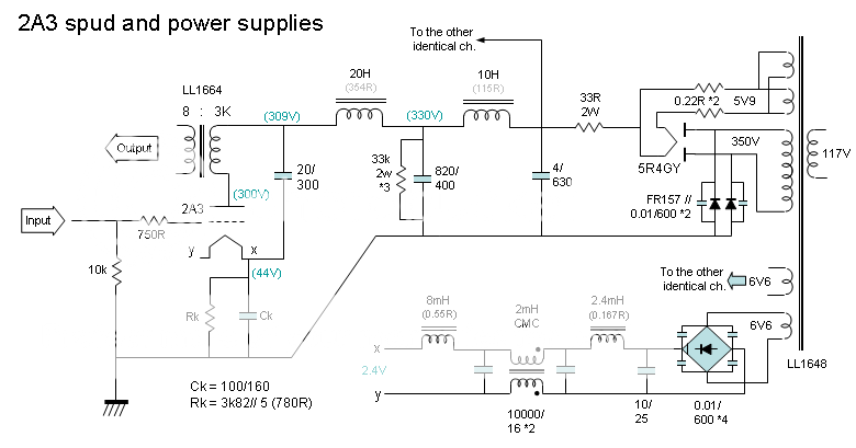
Maybe only one thing is worth mentioning - I planned to used LCLC filtering. Simulating by (not ideal) PSUD2 and got pretty much what I need. But in reality I just can not get the voltage as expected. So I add another small RC (33R+4uF) in front to get it there.
Similar situation happened in the heater power supplies. Voltage was far lower then planned. So I add 10uF here and reduce the inductance and DCR of the last choke to get 2.4V.
Oh, one more thing. I didn't use the cathode bypass cap in the beginning, but it buzz, big time. I planned to just rely on the WE connection (cap across OPT pri. and cathode), but interferences somewhere are too much. Putting the cathode bypass caps back on quiets it down immediately. Now there's a pretty pure 120Hz hum and it's quiet enough to ignore.
Everyone knows one 2A3 alone can never produce sufficient voltage gain for any source/speaker combo. So I'm cheating here with a very high gain pre amp - 417A/5842 with 1.125:1 OPT (reconfigured from 4.5:1 Lundahl LL1660). On paper, this pre (now driver) gives 135Vp-p (@ +/-2.1V input) and generous current drive for 2A3.
It's not a well-planned 'new' project. The major parts (irons and tubes) have been lying around for quite a long time, I just put them together now. And the aforementioned high gain pre amp is another major motivation. (I'd like to have as few stages as possible, now it's still two stages from DAC to speaker)
I'm lazy and hate metal work for amps, so I built it with (leftover) plywood. Other than those around tube sockets, I also drilled many holes around power and output transformers underneath for ventilation. These holes alone took me more than an hour. (However I was very happy it's not metal.)
The layout might be a little unusual. I put the tubes and OPTs at the rear for short signal paths. While the heaviest chokes and power transformer line up in the front makes it easier for me to lift/move. No looker, not to mention pretty, but I'm OK with that.
I own a 300B amp with a lot of irons which are in the rear half of the chasis (like most amps). With the load at the far side, it hurt my back several times. Ouch! 🙁
For a single stage triode, what can I do? It's all text book setup.
Maybe only one thing is worth mentioning - I planned to used LCLC filtering. Simulating by (not ideal) PSUD2 and got pretty much what I need. But in reality I just can not get the voltage as expected. So I add another small RC (33R+4uF) in front to get it there.
Similar situation happened in the heater power supplies. Voltage was far lower then planned. So I add 10uF here and reduce the inductance and DCR of the last choke to get 2.4V.
Oh, one more thing. I didn't use the cathode bypass cap in the beginning, but it buzz, big time. I planned to just rely on the WE connection (cap across OPT pri. and cathode), but interferences somewhere are too much. Putting the cathode bypass caps back on quiets it down immediately. Now there's a pretty pure 120Hz hum and it's quiet enough to ignore.
Member
Joined 2009
Paid Member
If you have sheilding / hum problems you can line the inside of the wood chassis with copper tape made by 3M. It is thin copper foil that has adhesive on one side and sticks to pretty much any type of surface.
Daniel
Daniel
Thanks for all your inputs🙂
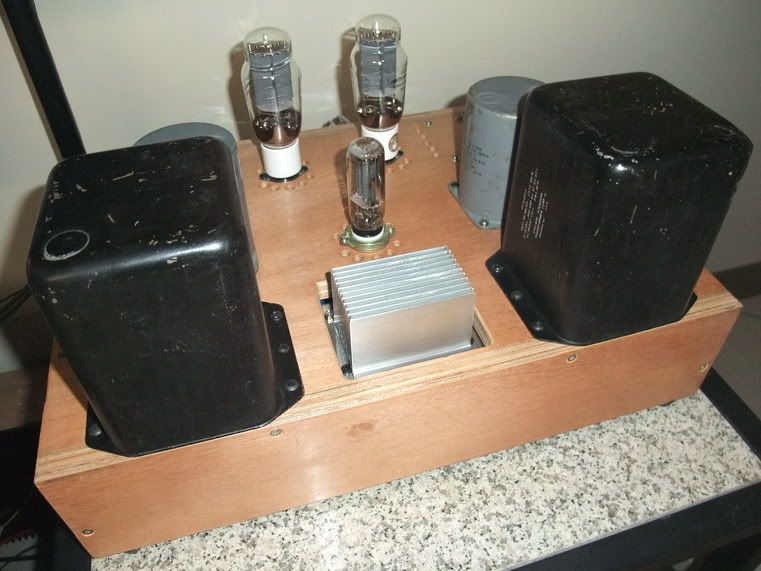
Sigh~ I'm just too lazy to take anymore effort in the finishing😱 I've applied 2 coats of bee wax (is that you call it?) on the outer surface, nothing was done inside. I'm just so eager to hear it, so built it in a hurry.
As to the possible buzz picking/interference, I'm still wondering. Last time I built a naked 6H30 spud amp on a piece of pine and got no problem. For many, that kind of build is bread board, but I just took it as it was, using it for about a year. It's dead quiet. (but that's not DHT, oh well)
I have some copper tape, but unfortunately it'd be too difficult to use it now, or I have to rebuild the whole circuit! Oh no! 🙁
The Lundahls should be very low in magnetic stray. Power chokes are sealed in their own metal case and should be OK, too. Maybe it's the choke(s) for heater supplies or they are not filtered well enough....
I'll take photo(s) of the inside later.
🙂
Oh, one more thing. I didn't use the cathode bypass cap in the beginning, but it buzz, big time.
I've applied 2 coats of bee wax (is that you call it?).......
Probably the bee's wax..........😛

The 4 EI chokes are for heater supplies. Two on the top were originally secured on the side wall with the cores pointing horizontally. Later I tried turning them as they are now, but no effect on the hum.
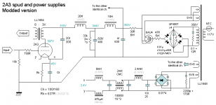
Other than the circuit diagram above, I added a small cap in front of the first RC as snubber. 0.47u as in the photo is too much, I swapped it to 0.22 later.
The 5R4GY has a bad behavior at the startup - huge voltage surge. It rushes to almost 400V on the OPT at its max and then fall down to 309V. Worrying about the 20u PIO bypass cap with only 300V rating, I tried IDH rectifier GZ37 (CV378). Now the startup behavior is much gentler but with a much less voltage drop and give me 20V more on the plate!
So now the plate voltage and dissipation exceeds the max 250V / 15W rating in the datasheet, but it seems fine and play well all day.
Or maybe I should turn the voltage down a little.
As to the possible buzz picking/interference, I'm still wondering.
🙂
Im no expert, but your trafos seem to form a "perfect" ring around your whole amp layout
might not be "optimal"
thats the first I noticed
but I dont know
what I usually notice is supply to one side, and amp section on the opposite
It might look that way, but actually not as simple 😉
2 heatsinks besides the power trafo are for bridge diodes of heater supplies. And along either side wall you see 2 (EI) chokes per side. Each 'path' of these 2 heater supplies is 'enclosed' itself by twisted wires. So they are very thin and twsited loops by themselves and form 2 large curves in an overall look.
And the HT supplies are more or less 'star' shape - thin blue/white twisted wires. Begin with the rectifier tube at the center, go to the 1st choke(s) at top coners, then back to filter caps in the middle, then go to the second choks(s), finally go down and feed the bypass cap and OPT. Each 'path' are twisted as far as possible. So I think the inner area of the 'loops' should be very small.
With the cathode bypass caps in place, now the hum is very low. I have to stuff my head into the mid horn to hear it. (this amp serves mid-high in active xover system only).
Updates with SS rectifier with damper diode
http://www.diyaudio.com/forums/tubes-valves/117948-freds-psu-6.html#post2299334
Not really settled, yet. Some work is still needed to tune the snubber, I guess.
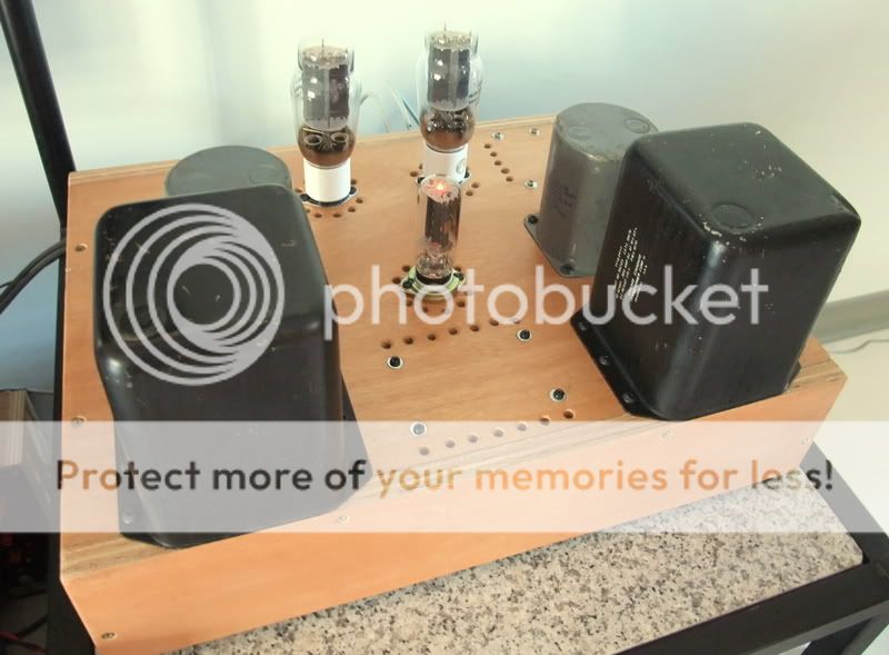
Small but very strong tube - 6AU4 (in the middde):
http://www.diyaudio.com/forums/tubes-valves/117948-freds-psu-6.html#post2299334
Not really settled, yet. Some work is still needed to tune the snubber, I guess.
Small but very strong tube - 6AU4 (in the middde):
More revisions
Some "patch work" was added or re-adjusted around rectifiers. Messy patches as they are, but they work! 😀
Some previous edginess brought by the UF4007 bridge was removed a lot and the HF is now very clean and detailed (if still a little bit bright). Interestingly, the power tranformer was buzzing a little and now calmed down completely. I thought to myself, the Lundahl should be as quiet as a stone, and this very trafo was indeed dead quiet in my last project, why it's buzzing now?
Stopping the trafo's buzzing must be a good sign for my snubber patch works 😀
And then I considered jacking up the bias current According to the previous experience with 300B, I like the sound of hot running tube. The 15W max dissipation on the datasheet bothered me somewhat, but the plate constrution of this EH 2A3 looks as big and as strong as a 300B! I don't believe it can only take that tiny 15W.
I spent some time digging into the old threads and found someone was burning the EH 2A3 and it worked fine.
So I did it. I reduced the series R in the first RC of filtering for the higher current requirement, and also reduced the cathode resistor (by adding one more resistor in parallel) to 637 Ohm.
Then the voltages on plate and cathode remain more or less the same but with higher current. Now it's 262V and 70mA, 18.3W dissipation.
The changes in sound is pretty much the way I expected. More powerful, punchier, effortless macro and micro dynamics, cleaner details, more focused, less fuzzy 'halos' around the images, less fake 'airy'... Simply put, I like it😀
Some "patch work" was added or re-adjusted around rectifiers. Messy patches as they are, but they work! 😀
Some previous edginess brought by the UF4007 bridge was removed a lot and the HF is now very clean and detailed (if still a little bit bright). Interestingly, the power tranformer was buzzing a little and now calmed down completely. I thought to myself, the Lundahl should be as quiet as a stone, and this very trafo was indeed dead quiet in my last project, why it's buzzing now?
Stopping the trafo's buzzing must be a good sign for my snubber patch works 😀
And then I considered jacking up the bias current
According to the previous experience with 300B, I like the sound of hot running tube. The 15W max dissipation on the datasheet bothered me somewhat, but the plate constrution of this EH 2A3 looks as big and as strong as a 300B! I don't believe it can only take that tiny 15W.I spent some time digging into the old threads and found someone was burning the EH 2A3 and it worked fine.
So I did it. I reduced the series R in the first RC of filtering for the higher current requirement, and also reduced the cathode resistor (by adding one more resistor in parallel) to 637 Ohm.
Then the voltages on plate and cathode remain more or less the same but with higher current. Now it's 262V and 70mA, 18.3W dissipation.
The changes in sound is pretty much the way I expected. More powerful, punchier, effortless macro and micro dynamics, cleaner details, more focused, less fuzzy 'halos' around the images, less fake 'airy'... Simply put, I like it😀
Attachments
Last edited:
Tubes gone bad, so soon?
4 EH 2A3 on hand, now 2 gone bad🙁
They have the same symptoms: lower gain and lower bias current.
On the 1st, I thought it might be in my initial stage of the project when it was probably switched on and off on the table too frequently. Or there might be chances that I moved the amp or tube when it's still too hot. So the internal parts might be deformed or something...
After that, I eased off my pace in modding. Touching it only when it's fully cool down or even over night. But here comes the 2nd one also gone bad in the same way last night.
Would it be I ran it too hot on the 2nd? + 20% of the max dissipation seems much, but the plate remained completely dark and calm. No gas, no strange color in the tubes. No noise, no detectable distortion, nothing unusual but good sound.
The bad one(s) only sound quieter. Listening in front of the speaker at its side, I can't hear any problem. Back to normal listening position, the images are all pulled to the other normal channel, at least half way off the center.
I've used 6H30, 6L6GC and 300B from EH and they were all good, strong and stable. I ran them very hot, too, and nothing like this.
Any idea?
Hi CLS, two tentative suggestions.
First--could there be positive voltages coming thru from your preamp? Leaky coupling caps kill output tubes more often than folk realize....2A3 grid volts should be 0V.
Second--maybe your 20uF/300VDC cap from B+ to 2A3 cathode is feeding low frequencies into the signal path. Re-attach it to ground as an experiment, nothing lost!! Except may lose that hum!
Cheers.
Last edited:
Thank you, but they seem not the real problems.
The pre amp (or driver) is transformer coupled, no DC issue. The grid leak resistor for 2A3 is a very low 10k Ohm.
And for the bypass cap(s), there are 2 in series - one encloses B+ and cathode; the other encloses cathode and ground. The residual hum is only audible 'in' the horn (105~107db/w).
I just figured it out last night. The "bad" 2A3 could probably be insufficient heater supplies, thus not enough emission to cope with the high bias current. They were measured 2.1V on the 2 'bad' tubes. On normal ones, there's 2.4V. So it's probably the deviation of manufacturing. The 'bad' ones are specially hungry. I'm working on it...
Oddly, there're 2 secondaries rated 6.6V 3A (0.1 Ohm DCR), but I got only 5.1Vdc after bridge rectifier and filter cap. Puzzling...
If I want to add voltage or current regulator, I'dd need to reconfigure it to voltage doubler....
I managed to fix the heater supply issue, calibrated the voltage to precise 2.5V by a 1% 1 Ohm resistor. This seemed to bring back the 'bad' tubes😀
Also, I re-config the B+ filter connections to CLCLCLC and lower the voltage somewhat. Now the well fed 2A3's flow 66~67mA @ 246~247Va / -42~-43Vg. They flow even more current than the graph on datasheet. It was late when I got it done, so didn't give it a good listen. Checked by a naked speaker driver, now the hum is even lower - my ear almost touched the cone to pick up the tiny sound. Well-filtered B+ obviously helps.
Next question: the driver is also a pre amp in a separate box and >1.5m away. I'm thinking eliminating the grid leak resistor of the 2A3 - all other transformer coupled circuits I've seen don't use that.
Other than 'run-away' by the badly-grounded gid, are there any other risks? If I can assure good inter-connetions, it should be fine. No?
This is because I'd like to have more current drive to the grid. Maybe it can drive it into slightly positive (A2) -- more head room 😀
Any suggestions?
Attachments
I was probably wrong or mixed up several things in listening impressions among these tunings😱 I was too impatient😱
Back when I switched to SS rectifier, the operation point was also shifted, and came the issue of 'bad' starved tubes. I must have mixed them all up - the brighter (or thinner) sound of SS diodes might probably be the starved filament supplies, at least by some portion.
Last night I gave it a good listen for an hour or two. The well fed 2A3's obviously sound fuller and richer. How I love it😀 My listening session was after I came back home from a piano solo concert in a local university. I'd say the piano sounds better in my home. And my families felt the same way. 😀
I guess there's more to come, but I really should slow it down and enjoy as it is for a while....
Update: Metal work
It's mentioned that I built this amp with plywood because I don't like doing metal work. However it seems unavoidable, sigh~
The rectifiers of filament supplies were so hot. After working about 1 hour, the small heatsinks become too hot to touch. The power transformer is very warm, too. ( I have to lift it somewhat and reach into the chassis from beneath to touch them. I know where to touch and where to avoid.)
They are all under the plywood case. Although I have drilled 2 rows of holes beside the transformer for ventilation, it seems not enough.
So here I cut it open and add some metal.
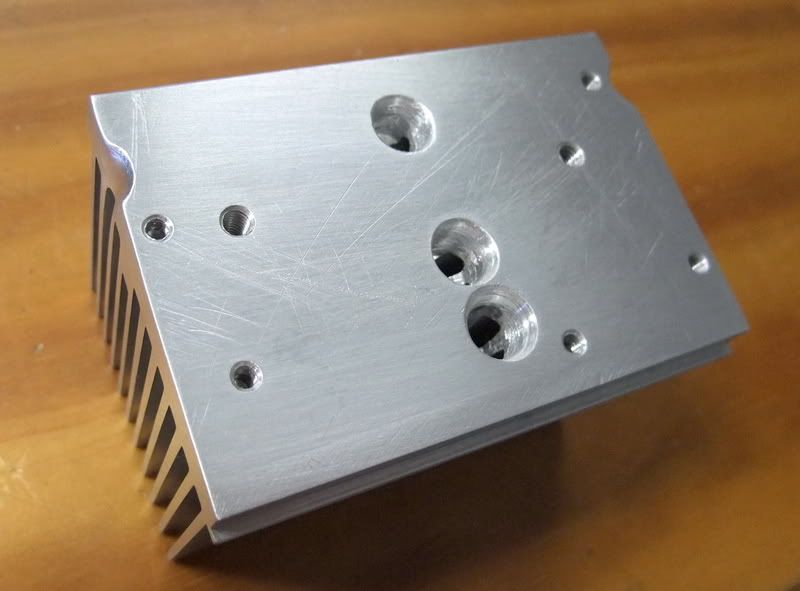
One of the element of the metal work is a bigger aluminum heatsink with denser fins. Not much freedom in mounting, the orientation of the fins is not ideal, so I drilled 3 holes on its base for some air flow through the middle, hopefully.
The other element is an L-shap aluminum board, 3 holes at the same position are drilled:
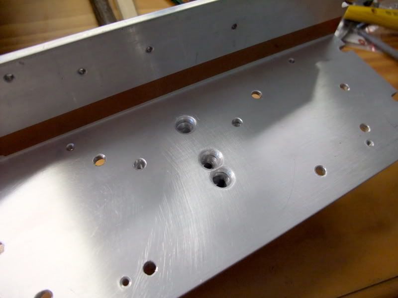
This side is carrying transformer and bridge diodes. The trafo is not directly attached to the mounting surface - if so, it'd be blocking those 3 ventilation holes, it's slightly separated by 3~4mm spacers.
Flip the assembly over, this should be the side up:
This is how they mounted in the chassis:
The aluminum board is not fully touching the plywood inner wall, there're also spacers for a gap.
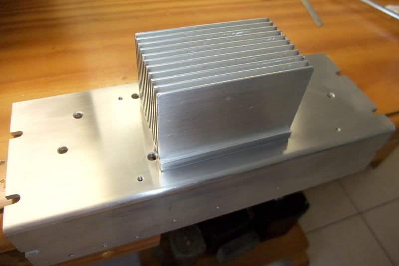
This is the complete view:
The heatsink is protruding through the hatch, and there's a gap around and underneath for air flow.
It looks alright, but it's still so hot! All the metal is not cooling it down, I'm still puzzling. And the temperature is rising quite slowly. It takes more than an hour to stable. After that, I can (only) hold my finger on it for 2~3 seconds. I guess it's over 70'C and not much cooler than the smaller heatsink before🙁
It's hotter than my previous Kinergetics KBA75 - a class A 75W SS amp. How can a 2x 2.5A supply do that? What's wrong with it?
Hot as it is, it seems working just fine for all day long. It just worries me.
Sigh~ should I give up the plywood case?
It's mentioned that I built this amp with plywood because I don't like doing metal work. However it seems unavoidable, sigh~
The rectifiers of filament supplies were so hot. After working about 1 hour, the small heatsinks become too hot to touch. The power transformer is very warm, too. ( I have to lift it somewhat and reach into the chassis from beneath to touch them. I know where to touch and where to avoid.)
They are all under the plywood case. Although I have drilled 2 rows of holes beside the transformer for ventilation, it seems not enough.
So here I cut it open and add some metal.
One of the element of the metal work is a bigger aluminum heatsink with denser fins. Not much freedom in mounting, the orientation of the fins is not ideal, so I drilled 3 holes on its base for some air flow through the middle, hopefully.
The other element is an L-shap aluminum board, 3 holes at the same position are drilled:
This side is carrying transformer and bridge diodes. The trafo is not directly attached to the mounting surface - if so, it'd be blocking those 3 ventilation holes, it's slightly separated by 3~4mm spacers.
Flip the assembly over, this should be the side up:
This is how they mounted in the chassis:
The aluminum board is not fully touching the plywood inner wall, there're also spacers for a gap.
This is the complete view:
The heatsink is protruding through the hatch, and there's a gap around and underneath for air flow.
It looks alright, but it's still so hot!
All the metal is not cooling it down, I'm still puzzling. And the temperature is rising quite slowly. It takes more than an hour to stable. After that, I can (only) hold my finger on it for 2~3 seconds. I guess it's over 70'C and not much cooler than the smaller heatsink before🙁It's hotter than my previous Kinergetics KBA75 - a class A 75W SS amp. How can a 2x 2.5A supply do that? What's wrong with it?
Hot as it is, it seems working just fine for all day long. It just worries me.
Sigh~ should I give up the plywood case?
OK here is the filament supply.
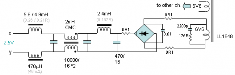
The secondary is rated 6.6Vac, 0.1 Ohm DCR, 3A capacity. Prior to the bridge, total DCR in addition to the coil is 0.3 Ohm.
After the bridge, there're one small series R (0.1 Ohm), and 4 chokes (one of them is CMC). Total DCR should be within 0.6x Ohm.
470 uF as the 1st filtering cap for lower chage current, 2 x 10000uF after a 2.4mH choke.
I got 2.5V and 2.5A at the output.
I can not use PSUII for simulating all of the above. With simplified components, I got a result very close to what I got in reality.
The voltage on the 1st 470uF cap is about 3.7Vdc. In an ideal no load rectified and filtered circuit, it should be 6.6 x 1.414 = 9.33 Vdc.
Let's assume all that voltage drop happens in the bridge. Then (9.33 - 3.7) * 2.5A = 14W, two of them would be 28W.
Is 28W that hot?
While the loss wouldn't be all in the bridge, and some of them should be spreaded among caps and components in serial...
😕
Attachments
- Status
- Not open for further replies.
- Home
- Amplifiers
- Tubes / Valves
- 2A3 Spud