Hi Gregg,
Thanks for the tip, will try. I did that only in calibrating filament supply voltage for a short period without observation to the heat.
It stayed stable at precise 2.5V in a 3 hour full amp test, though. It's upside down during that test. With the fully open bottom facing up, I expected a better cooling but no. Heatsink, power transformer, and bridge diodes are still as hot as normal position.
Other components are all mildly warm or cool, and it's working OK.
OK, I just figured that out. Well, sort of.
Playing with PSU II, I found I made a mistake in choosing a small 1st cap after the rectifier. I planed to reduce the charge current and less current spike, thus lowering the noise.
However, smaller caps tend to have higher impedance at the mains frequency. Playing the impedance in PSU II, I found the voltage across the bridge would be higher as the 1st cap's impedance goes higher. This explains why I got the output voltage so low and a bridge so hot. It's so elementary and I'm embarrassed not handling it well😱 The only excuse is this is the 1st time I encounter 2.5V 2.5A circuit 😱
I'll try re-arranging the caps and chokes. Maybe I'll get a couple of volts to spare, at least for a simple current reg (by a low drop out Vreg)😀
Just a thought,
If your initial cap is low uF and the drain is high the supply will be trying to continualy charge the capacitor. This also means that the pressure on the diodes will be low from the capacitor due to discharge. Volt drop will be high. If the cap is a higher value the initial charge current will be high, however the cap will be able to supply a discharge for longer. So the back pressure will be greater and the voltage drop across the diodes will be lower.
Next thought.
If the charge time constant is to long "cap to large" the cap will never reach full charge and again the volt drop across the diodes will be high.🙂
Basic I know, this is always a compromise with higher current supplies. As you say impedance will effect time constant!
Regards
M. Gregg
Last edited:
I managed to re-arrange the filtering caps of the filament supply and get a proper voltage. I got 6.2V on the 1st 10000uF cap and 5.7V on the 2nd (after a 2.4mH choke) - good for a low drop out Vreg to work, so I did it.
The CCS setup is very simple, just a 3-leg Vreg (LD1085). Final goal is 2.5V on the filament, plus 1.25V reference voltage, it leaves 1.95V for dropout, well above rated 1.5Vmax (@5A).
I use a measured-good 0.5 Ohm fixed resistor for the 1.25Vref sensing to get exact 2.5A current flow. However this give me 2.6V on the filament. So it seems the hot resistance of filament is not at precise 1 Ohm (1.04 instead). Or maybe my 0.5 Ohm and the Vref of the chip are not that precise, too. (Gee! these small numbers.... )
Later I added some more resistors (some 0.1R in parallel) to turn down the voltage. Now it's perfectly set at 2.5V. Meantime, I got an observation of the B+ vs Ia. I found higher filament voltage yeilds more Ia. In the process of tuning, the filament voltage changed in very small amount, while the Ia reflects the filament supply power very sensitively. The voltage (power) on the filament directly reflects its emission, thus the current flow.
This also got me thinking that I fiddled the operation points around was probably not a good thing. Emission is also a key point that I ignored and should not be changed widely. This factor sets the 'proper' proportion of the other 2. Who (the xxxx) am I to challenge RCA manual? So, I tuned it back to approach the text book numbers.
The 2nd observation is the noise, or how it's been attenuated. It's DEAD QUIET by this simple CCS. In previous CLCLCL filter, I had to attach the test driver to my ear to hear the very little hum. Now I get NO sound at all!
3rd discovery is, sound quality wise, I can't tell the difference between CCS (by Vreg) and choke filter. I really can't. They are equally good. I don't hear what others said. Bad hearing? I don't know. 😱 (I don't have enough voltage to spare, for a better CCS anyway, oh well... )
4th, they are hot! The aforementioned aluminum board and heatsink for transformer / bridge diode are as hot as before. The newly added CCS (on it's own heatsink) is at similar temperature. (on which I can only keep touching for a couple of sec.) 🙁
I didn't make the heatsinks of CCS stand out of the chassis, they're fixed inside. I just drilled some holes above it for convection. After using for a whole afternoon, they are quite hot (working perfectly with great sound, though). So I tuned the voltage again to make the drop out slightly lower to 1.65V. By calculation, it only dissipates several W each, why so hot? Strange....
5th observation is about the startup behavior. B+ is mainly controlled by the slow turn-on TV damper diode. It's nothing in the first 20 sec. or so, then taking another 10 sec. or slightly more to rise to the working voltage. So it's about 30 sec. in totall, give or take. OTOH, in the same period, the filament voltage only get to about 2.3V (the progree is very linear, though, after the initial 0.4~0.5V jump start). It needs quite some more time to get to 2.5V. (any slower damper diode?)
BTW, the previous 1A slow-blo fuse on mains opened after about 10 min. after the 1st trial of new filtering and CCS. Checked everything, I inserted another fuse (at the same rating). This one warmed up the fuse holder quite obvious, not to its death, I changed again. The 3rd one worked OK on the table for about 1 hour, but it died in 10 min. after hooking up to the system. That fuse had been working OK with various setup stages and survived, died on the change to the filtering of filament supply (?)
Except for running hot, nothing wrong in the amp, so I changed a slightly bigger fuse, 1.25A fast-blo. This one works OK and stays cool, for now.
That's all.
...
3rd discovery is, sound quality wise, I can't tell the difference between CCS (by Vreg) and choke filter. I really can't. They are equally good. I don't hear what others said. Bad hearing? I don't know. 😱
....
A side note for this:
The previous filter is CLCLCL --
470uF - 2.4mH - 10000uF - 2mH CMC - 10000uF - 5mH
(in fact there's another small choke at the return leg of the last C)
So there was no cap in the end. Filament saw chokes, not cap. I guess this helped somewhat.
Any comments on the hot power transformer and bridge rectifiers? 🙁
This very transformer was used in my previous 6H30 project. With a lot less current on HT and LT secondaries, it was also quite warm then. It could be touched continually, but very warm. Now it seems reasonable hotter with much more current draw. No?
The power transformer in my pre amp is also a Lundahl, same VA capacity with different voltages. It serves 4* 417A/5842 @ 16~18mA each and 2 * 1.2A for rectifier tubes, is also quite warm to touch. So maybe it's normal?
Can't compare directly, a reference though -- the power transformer in my 300B amp is also hot. The largely perforated metal top cover above it is very hot to touch, let alone the trafo itself. It's not built by me (I did some mods only). It's a commercial available product.
Another example I remember is JC Verdier 300B I had borrowed from a friend and used for a while. It's hot all over! Small chassis and 3 large (potted) transformers are all very hot to touch. Ouch!
Am I overreacting? Any inputs?
I'm talking to myself here... Oh well.
Per (Lundahl) answered my email just now, stated that their power transformer should operate under 80'C. That's very hot and can burn! I can't really tell if mine exceeds that number, but very unlikely.
I'll go buy a thermometer.
Per (Lundahl) answered my email just now, stated that their power transformer should operate under 80'C. That's very hot and can burn! I can't really tell if mine exceeds that number, but very unlikely.
I'll go buy a thermometer.
I'm talking to myself here... Oh well.
Per (Lundahl) answered my email just now, stated that their power transformer should operate under 80'C. That's very hot and can burn! I can't really tell if mine exceeds that number, but very unlikely.
I'll go buy a thermometer.
A transformer normaly runs hot if it is under rated, or working close to its maximum output.
To check this measure the current taken from each winding multiply it by its voltage this gives the wattage for each. Add them all togeather (O.K. this is not the true VA, however its close excepting losses) compare this to the VA of the transformer! you should allow a margin!
If the rating of the Tx is not exceeded then it should be within manufacturers spec temperature!
The more "headroom" you have the cooler will be the TX. Another point to note is your snubber networks across rectifiers. Take care that you are not creating a low impedance short!
An example of this is putting a 0.01 uF cap across a contact with mains at 50Hz it will appear to be in conduction when the contact is open! just a thought!🙂
Regards
M. Gregg
Last edited:
Thanks for inputs 🙂
Good to know I'm not alone. Here is how I use it:
1. sec. #1 (350V): capacitor (4uF) input rectifier, DC output is 120mA
2. sec. #2&3 (5.9V): parallel and feed the heater of rectifier tube, 1.8A
3. sec. #4&5 (6.6V): capacitor (10000uF) input rectifier and current regulated at 2.5A each.
So it's 350x0.12 + 5.9x1.8 + 6.6x2.5.2 = 42 + 10.6 + 33 = 85.6 (VA) in total.
Ah~ sure this is not the real consumption. Many factors are not taken into consideration - losses here and there.... And this trafo is rated 250VA.
It seems the load is a peice of cake for it. However there's a catch.
The 6.6V secondaries (I'm using for 2A3 filament supply) is rated 3.1A output. And there's note in datasheet:
" Output current from rectifier: 63% of above with condensor input rectifier, 95% of above with choke input rectifier. "
So, 3.1A x 63% = 1.95A is the upper limit of output current for cap input filtering. While I forced them doing 2.5A.
And in the web site of Lundahl, it's said "For optimal use, about 75% of power should be taken from secondary 1". Hmmm... sec#1 is the HT winding, in my amp, only half of the power is for HT. Filaments eat up the other half.
But Per said it's OK in my application, given the air circulation is good. Oh no, it's not so good🙁 I managed to make the ventilating gap a little larger last night. Some other works were not finished, so not tested it yet.
The thermometer is on the way. I'll get exact number once I have it.
As to those snubbers, I did think of those caps, too. The biggest cap is the 0.1 uF (with 12R) on the 350V winding. With the resistance of winding (20R), that forms a high pass filter of 49.7kHz (-3dB). So I think it should be OK at mains 60Hz (here).
I think they are simply stating the max the transformer is specified for is with a choke input filter. Going to capacitive input filter means you have to derate the load (less current but you get more voltage, ie same VA).
Optimum is simply full loading of each individual winding.
You might get by pulling slightly more from a heater winding IF you reduced the other winding loads, but this is not "optimum".
If each of your loads is less than the rated load for the winding, everything is 'fine as frog hair'.
Optimum is simply full loading of each individual winding.
You might get by pulling slightly more from a heater winding IF you reduced the other winding loads, but this is not "optimum".
If each of your loads is less than the rated load for the winding, everything is 'fine as frog hair'.
Remember you are measuring RMS not peak voltage on AC.
You can now check your input mains current and voltage and compare the losses. "Heat is a loss".
Just for interest! This would be interesting regards your warm fuse from a previous post!
You say your 6.3V winding can supply 3.1A so it is within spec for output current although it is not correct to the usage criteria in the data sheet. As long as you are not exceeding the VA per winding it should be O.K.
Regards
M. Gregg
Last edited:
Fuses run warm. They are resistors. They operate by thermally fusing the wire when overloaded. I've measured fuse temps as high as 85C under normal operating conditions. Especially if inside an inclosed fuse holder.
The choke vs cap input filter is refering to the B+ winding as most people will use either choke input or cap input filter and B+ is by definition rectified.
Mosts people do not rectify heater supplies and those are specified only at ac.
Either of Sec 2 or Sec 3 can drive your rectifier tube.
This leaves you with Sec 4 and 5.
Each if rectified and filtered can only supply 3.1/1.414 =2.19A. So if each is driving a 2.5A load, they are overloaded by 8.77%. Since this is less than 10% overload and your overall load is way less than max it is probably ok.
Since Sec 1, 2 and 3 are loaded below spec, this may be oK as the total power demand is below the VA rating of the transformer, however I would contact Lundhal and ask them if it is ok as it will cause windings 4 and 5 to run hotter than spec. It depends on the winding topology of the transformer.
You will not be able to measure this (higher temp on sec 4&5) with a thermometer as you can not access the internal layers of the transformer. The outer transformer temp will be below max spec as it is running well under max spec dissipation.
Fuses run warm. They are resistors. They operate by thermally fusing the wire when overloaded. I've measured fuse temps as high as 85C under normal operating conditions. Especially if inside an inclosed fuse holder.
The choke vs cap input filter is refering to the B+ winding as most people will use either choke input or cap input filter and B+ is by definition rectified.
Mosts people do not rectify heater supplies and those are specified only at ac.
Either of Sec 2 or Sec 3 can drive your rectifier tube.
This leaves you with Sec 4 and 5.
Each if rectified and filtered can only supply 3.1/1.414 =2.19A. So if each is driving a 2.5A load, they are overloaded by 8.77%. Since this is less than 10% overload and your overall load is way less than max it is probably ok.
It would be interesting to know how much "headroom" Lundhal build into their Power Tx for safety. I wish manufacturers would not regard such temperatures as "normal". Maybe to them it is!🙂
hi CLS,
I believe the Lundahl LL1648 power transformer has sufficient power for such low power 2A3 power amp.
First of all, I would suggest to use just single secondary 5.9V winding for the rectifier tube's filament supply. Each 5.9V winding is rated for 3.1A. The 5R4 filament current is only 2.0A.
It would be very helpful if you can find a AC/DC clamp meter to measure the current at each circuit so that you know which circuit takes exceptional high current.
It should be that HOT>>>>>
Johnny Tang
By the way, did you measure the voltage at the 2A3's filament if the voltage is correct??
I woulld put a separate 2 x 2.5V power transformer so that it is powered by AC to simplify the whole circuit with much less HEAT.....
Johnny
I woulld put a separate 2 x 2.5V power transformer so that it is powered by AC to simplify the whole circuit with much less HEAT.....
Johnny
Thanks a lot for all your inputs🙂
Some points:
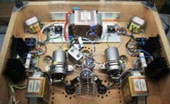
1. The low voltage windings (2x 5.9V, 2x 6.6V) are on the most outer layer. This can be confirmed by just tracing back the terminals (by its open structure). Also, the wire gauge here is obviously big with very few turns - through the semi-transparent insulation, it's easily seen. This might be a good thing for losing heat of these particular windings. (?)
2. I parallel the 2* 5V9 windings because there's no other usage. And Lundahl suggests the "2 sides" of windings see balance loads for minimum magnetic stray. I no longer use 5R4, now it's 6AU4GTA, with 6.3V / 1.8A heater. I think parallel coils yield even less voltage drop, slightly compensating the not-up-to-the-spec supply voltage.
3. Ah! clamp meter, good stuff, I don't have it🙁
4. According to the home appliance safety standards (UL, CSA, EN, IEC... etc.), acceptable temperture rise of class A (105) windings is 65 degree by thermal couple method. Please note this is the 'rise' portion, so if room temperature is 25 degree C, than it's 25+65=90. Since class A (105) is the lowest grade of any certified enamelled copper wire and insulation materials, so Lundahl's claim of 80 degree is very conservative. BTW, Per said the epoxy sealing would get soft beyond 80 degree and the windings are going to hum, he did not mention any real hazard or catching fire etc.
-- I did know that, but haven't had such temperature in my own builds. And I really don't like it so hot 🙁 --
I haven't had my thermometer yet. I'll get the number to see exactly how hot it is. I really don't think it's beyond 80 (I don't think I can hold that for 2~3 sec. )
5. The voltage of 2A3's filament is now controlled by the current of CCS supply. It's fine tuned to perfect 2.5V (with slighly less than 2.5A). The drop out of the Vreg and other components are all fine.
A separate transformer, oh yes, I'm considering. I actually enquired some local winders these days. I'm still struggling between 'keep it simple as it is' or 'make it as perfect as possible'.... As to AC vs DC, I still prefer DC (even with all these troubles). The sensitivity of my speaker is very high, and I like it without hum. Later current source supply kills all the hum really impresses me. The residual hum of previous choke filtered supply is also very low, but compared to NONE, well.... One another major benefit of separate transformer for filaments is I can add even more delay to the HT supply, for compensating the slow-rising voltage and temperature of the filament choked by the CCS.
More to come....
Some points:
1. The low voltage windings (2x 5.9V, 2x 6.6V) are on the most outer layer. This can be confirmed by just tracing back the terminals (by its open structure). Also, the wire gauge here is obviously big with very few turns - through the semi-transparent insulation, it's easily seen. This might be a good thing for losing heat of these particular windings. (?)
2. I parallel the 2* 5V9 windings because there's no other usage. And Lundahl suggests the "2 sides" of windings see balance loads for minimum magnetic stray. I no longer use 5R4, now it's 6AU4GTA, with 6.3V / 1.8A heater. I think parallel coils yield even less voltage drop, slightly compensating the not-up-to-the-spec supply voltage.
3. Ah! clamp meter, good stuff, I don't have it🙁
4. According to the home appliance safety standards (UL, CSA, EN, IEC... etc.), acceptable temperture rise of class A (105) windings is 65 degree by thermal couple method. Please note this is the 'rise' portion, so if room temperature is 25 degree C, than it's 25+65=90. Since class A (105) is the lowest grade of any certified enamelled copper wire and insulation materials, so Lundahl's claim of 80 degree is very conservative. BTW, Per said the epoxy sealing would get soft beyond 80 degree and the windings are going to hum, he did not mention any real hazard or catching fire etc.
-- I did know that, but haven't had such temperature in my own builds. And I really don't like it so hot 🙁 --
I haven't had my thermometer yet. I'll get the number to see exactly how hot it is. I really don't think it's beyond 80 (I don't think I can hold that for 2~3 sec. )
5. The voltage of 2A3's filament is now controlled by the current of CCS supply. It's fine tuned to perfect 2.5V (with slighly less than 2.5A). The drop out of the Vreg and other components are all fine.
A separate transformer, oh yes, I'm considering. I actually enquired some local winders these days. I'm still struggling between 'keep it simple as it is' or 'make it as perfect as possible'.... As to AC vs DC, I still prefer DC (even with all these troubles). The sensitivity of my speaker is very high, and I like it without hum. Later current source supply kills all the hum really impresses me. The residual hum of previous choke filtered supply is also very low, but compared to NONE, well.... One another major benefit of separate transformer for filaments is I can add even more delay to the HT supply, for compensating the slow-rising voltage and temperature of the filament choked by the CCS.
More to come....
Last edited:
I'm totally embarrassed about the temperature measuring.
What I got is a thermometer for cooking - used for stabbing into the object under measurement, like cake, fluid... etc. When used for picking up surface temperature, it seems not so effective, and I highly doubt it's accuracy.
Say, the aforementioned 'too hot to touch continuously' heat sink (for bridge and PT), was measured only 50 degree C !!
Heatsinks for Vreg was measured at 43'C, which I feel still hot but can touch continuously.
Cooled by a little fan, the 'measured' 50'C PT can get down several degree to about 45 and continuously touchable...
Is it my sense of temperature has too little tolerance 😱, or the thermometer isn't up to the job? Had proved it in boiling water and it seemed working fine showing me 100.7 'C. However, that's what it designed to do - surrounded by the measured object, and different heat transfer situation from a flat solid surface where the contact patch is so small...
I don't remember where or when I got the impression that the temperature of 'too hot to touch' is above 60~65 degree C. And now this😱
Looking for other measuring tool....
- Status
- Not open for further replies.
- Home
- Amplifiers
- Tubes / Valves
- 2A3 Spud