It does, but it screws the whole compensation scheme of the composite. The noise gain trick can only be used on the outer opamp.
So what happens in a scenario where one of the pins isn't grounded? For example what if you place a resistor between the + and - pins on the second opamp in the composite shown in the paper?
Neither pin is truly grounded, does it still increase the noise gain while maintaining the signal gain of the second opamp?
Don't think of the composite as separable stages. Treat it as a blackbox generic op-amp. Doing what you ask would fundamental changes the nature of the composite, especially with the complication of Groner's 'internal' compensation networks.
Okay so here is my set-up

I'm using an LT1364 opamp in inverting mode with 1k and 10k feedback resistors and a 10 ohm noise gain resistor. The load is 100 ohm and the output voltage swing is 4.32v P-P.
Unfortunately when I went from 10 ohms to 5 ohms the distortion got better for some reason so I went with 10 ohms. This only gives me about 30 db extra headroom. I prefer the method of dragging amplifier down by running it out of spec because I can make it distort much worse but this is what you guys wanted so here it is.
This is the distortion without the 10 ohm noise gain resistor.

This is the distortion with the 10 ohm noise gain resistor.

This is the distortion when applying the most basic form of my EC

Unfortunately I couldn't make my EC worse unless I specifically tried to. This is the bottom of the barrel and it's already near the noise floor. I prefer my method of loading down the amp.
Also a huge portion of my EC is straight up incompatible with this noise gain resistor method. The resistor completely ruins the performance of the EC. Fortunately different sections of my EC are able to be separated from each other but I can only go so far with that resistor in place. However I can at least double the performance gain of the above measurement even with the resistor in place, maybe triple if I'm really lucky and get creative, but the noise floor problem still remains.I'm all ears, I'm letting you guys lead me on this one.
I'm using an LT1364 opamp in inverting mode with 1k and 10k feedback resistors and a 10 ohm noise gain resistor. The load is 100 ohm and the output voltage swing is 4.32v P-P.
Unfortunately when I went from 10 ohms to 5 ohms the distortion got better for some reason so I went with 10 ohms. This only gives me about 30 db extra headroom. I prefer the method of dragging amplifier down by running it out of spec because I can make it distort much worse but this is what you guys wanted so here it is.
This is the distortion without the 10 ohm noise gain resistor.
This is the distortion with the 10 ohm noise gain resistor.
This is the distortion when applying the most basic form of my EC
Unfortunately I couldn't make my EC worse unless I specifically tried to. This is the bottom of the barrel and it's already near the noise floor. I prefer my method of loading down the amp.
Also a huge portion of my EC is straight up incompatible with this noise gain resistor method. The resistor completely ruins the performance of the EC. Fortunately different sections of my EC are able to be separated from each other but I can only go so far with that resistor in place. However I can at least double the performance gain of the above measurement even with the resistor in place, maybe triple if I'm really lucky and get creative, but the noise floor problem still remains.I'm all ears, I'm letting you guys lead me on this one.
Last edited:
Also a huge portion of my EC is straight up incompatible with this noise gain resistor method.
This is not going to go well, on the surface this makes no sense the resistor simply amplifies the input error signal it is completely out of any amplifier/EC loop. I think this is all going to be a waste of time unless you get a partner with a deeper understanding of the design process.
BTW I'm sorry for your situation and anxiety about it.
It would make sense if you saw the schematic of my EC, trust me. That portion of the circuit only matters if I'm trying to eek out every drop of performance anyway. It was my mistake for even mentioning it as it is effectively irrelevant. I already got a 40db improvement with the resistor in place and I can still make it 2-3 times better than that result even with the resistor in place. But damn, you gave up on me fast. Unfortunately I will find such a partner, I know better.
Last edited:
It would make sense if you saw the schematic of my EC, trust me.
I doubt it. Give up, I'm waiting for the DM plots first. BTW the resistor is essentially the same as the DM see for instance Bob Pease's Nat semi datasheets.
Just consider this: -290dB SiNaD would require 25MA current (shot noise) and signal power of 33TW (Johnson noise).
A 32 bit sampled hour of audio with just 1 LSB flipped would exhibit -269dB of change accrued over the entire hour.
And of course at some point passive component non-linearities will take over, perhaps by -170dB or so (wild guess). All resistors have voltage coefficients, no conducting material is perfect.
It would make sense if you saw the schematic of my EC, trust me. That portion of the circuit only matters if I'm trying to eek out every drop of performance anyway.
It was my mistake for even mentioning it as it is effectively irrelevant. I already got a 40db improvement with the resistor in place and I can still make it 2-3 times better than that result even with the resistor in place.
But damn, you gave up on me fast. Unfortunately I will find such a partner, I know better.
I admire your ambition, but since you don't know what noise gain is, I find it really unlikely you have designed some groundbreaking error correction circuit. It's more likely that SPICE is fooling you and all of your measurements are artifacts.
Did you plan to patent this? Did you search for prior art? It will be reverse engineered in 5 minutes anyway if it does work.
Last edited:
Hello,
Bach when, before Burr Brown became Texas Instruments Jerald Graeme created the distortion multiplication / feedback procedures to measure distortion level lower than the AP state of the art audio analyzers of the time. To see the results see the TI datasheet for the LM4562 Operational amplifier. Figure 109.
http://www.ti.com/lit/ds/symlink/lm4562.pdf -150.46dB
Also June 20, 1991 EDN pg 139
looks just like the method used by hellokitty123 post 163.
Thanks DT
Last edited:
LMAO.Edit: Hey mod, could you name the thread something a little less boasty and errogant? Kinda not my style.
Thanks! 😀
Hello,
looks just like the method used by hellokitty123 post 163.
Thanks DT
Old news Walt Jung and I published it in 1982.
https://www.analog.com/media/en/technical-documentation/application-notes/5866763300941AN245.pdf
I'm hijacking onto the rectifier diodes in the DM to power it. Having some issues getting it working though. The signal is not nulling. I had configured the DM to be set for unity gain last time I used it so I set my test amp to unity as well but the signal does not completely null and the phase controls are not having any effect. At its lowest point the signal is still magnified quite a bit over the original signal. I'm connecting the oscillator to the "source" input and connecting the DUT to one of the "amp" inputs and grounding the other. I've tried both positions. Magnification is set to "null" and gain is set to X1. I even tried connecting the oscillator to both the "source" and "amp" inputs simultaneously which should have worked. Am I forgetting something?
Last edited:
I'm hijacking onto the rectifier diodes in the DM to power it.
And you are sure you didn't create a ground loop or some other issue that way?
No ground loop, everything is powered by the same supply, only one ground point. I reconfigured the DUT input stage back to its default 0.1X gain and put the test amp back to 10x gain to see if there was a difference and it was effectively the same result. I haven't touched the DM since I last used it so I don't think it's broken. I must be doing something incorrectly.
By the way what's up Markw4, been a while since we talked. I've been overwhelmingly busy since then.
By the way what's up Markw4, been a while since we talked. I've been overwhelmingly busy since then.
Last edited:
By the way what's up Markw4, been a while since we talked.
Still interest in dacs here. Main difference is met a very experienced high end audio analog designer. Some of our conversing may be applicable to dac work, only time will tell.
I hope your situation is less worrisome than it was at one point. The other guys are probably right that at some point you will have to confide whatever you are doing to someone you trust with more electronics knowledge than you currently have. The other guys are quite justified to suspect you are doing something wrong with your testing. They can't help you until you reveal more, and you can't do it all yourself without a lot more electronics education. Tough situation from your viewpoint with no apparent both safe & short-term solutions.
if you truly have -289 db you are a billionaire, this will revolutionize more than space craft.
Just consider this: -290dB SiNaD would require 25MA current (shot noise) and signal power of 33TW (Johnson noise).
A 32 bit sampled hour of audio with just 1 LSB flipped would exhibit -269dB of change accrued over the entire hour.
And of course at some point passive component non-linearities will take over, perhaps by -170dB or so (wild guess). All resistors have voltage coefficients, no conducting material is perfect.
Passive component nonlinearity is indeed an issue, but why do people keep mixing up SINAD with harmonic distortion all over this thread? The thread starter never claimed to extrapolate 290 dB SINAD.
To get a gut feeling for 290 dB:
A VHF signal leaving earth, travelling 380000 Km to the moon, being reflected by the stones, craters and dust there and travelling back 380000 Km to earth is attenuated by about 274 dB.
Cheers,
Gerhard
A VHF signal leaving earth, travelling 380000 Km to the moon, being reflected by the stones, craters and dust there and travelling back 380000 Km to earth is attenuated by about 274 dB.
Cheers,
Gerhard
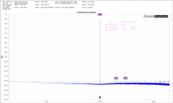
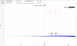
Okay so here is my set-up
I'm using an LT1364 opamp in inverting mode with 1k and 10k feedback resistors and a 10 ohm noise gain resistor. The load is 100 ohm and the output voltage swing is 4.32v P-P.
Unfortunately when I went from 10 ohms to 5 ohms the distortion got better for some reason so I went with 10 ohms. This only gives me about 30 db extra headroom. I prefer the method of dragging amplifier down by running it out of spec because I can make it distort much worse but this is what you guys wanted so here it is.
This is the distortion without the 10 ohm noise gain resistor.
This is the distortion with the 10 ohm noise gain resistor.
This is the distortion when applying the most basic form of my EC
Unfortunately I couldn't make my EC worse unless I specifically tried to. This is the bottom of the barrel and it's already near the noise floor. I prefer my method of loading down the amp.
Also a huge portion of my EC is straight up incompatible with this noise gain resistor method. The resistor completely ruins the performance of the EC. Fortunately different sections of my EC are able to be separated from each other but I can only go so far with that resistor in place. However I can at least double the performance gain of the above measurement even with the resistor in place, maybe triple if I'm really lucky and get creative, but the noise floor problem still remains.I'm all ears, I'm letting you guys lead me on this one.
I think this is the most clear set of graphs yet in this thread. The amp on itself has a distortion of -80dB and the noise gain trick isn't really necessary to measure it. It appears that your EC lowers the distortion by 40dB, getting to -120dB. That is quite worthwhile, depending on the complexity of the EC.
One next step could be to make your amp better by another 20dB, and tweak your EC another 10dB, which would bring the combo to -150dB. If this can be sustained over frequency you got yourself a hell of an amp.
Jan
Last edited:
- Status
- Not open for further replies.
- Home
- Source & Line
- Analog Line Level
- -290 dB Distortion?