A 10 Ohm resistor noise is about 410 pV/rtHz or about 60nV over a 20 kHz audio bandwidth. You can't measure or see anything below this without using some kind of synchronous filtering and detection. So I'd say a safe bet is to assume the absolute best case you will get is -144dBV. But this ignores the active component noise/distortion contributions which - lets be generous here - will be at least an order of magnitude higher.
We have not considered resistor voltage coeff - on a really good resistor about 1-2 uV per volt. To keep it at this level on a power amp, you could put a whole lot of resistors in series for the feedback arm, but you won't get better than 1uV/Volt
This is why even using the noise resistor method, you don't get better than c. 100-200 ppb (LM4562 data sheet stuff)
-290 dB is LIGO territory . . . .
But that's the problem. The -40db improvement was too easy to achieve with my circuit. If I do anything else I end up adding another -40db. I mean I've already shown in one of the previous screenshots an improvement of over -100db and that was only 40% of the full circuit. The conditions of that test were the same as the one you just commented on. The only difference was I made LT1364 output 12.9v p-p into the load instead of 4.32v p-p and the use of a 10 ohm noise gain resistor to make the amp distort. Here was the post -290 dB Distortion?I think this is the most clear set of graphs yet in this thread. The amp on itself has a distortion of -80dB and the noise gain trick isn't really necessary to measure it. It appears that your EC lowers the distortion by 40dB, getting to -120dB. That is quite worthwhile, depending on the complexity of the EC.
One next step could be to make your amp better by another 20dB, and tweak your EC another 10dB, which would bring the combo to -150dB. If this can be sustained over frequency you got yourself a hell of an amp.
Jan
I'm trying to get my damn DM working here but the thing won't null for some reason, it's frustrating.
Last edited:
Still interest in dacs here. Main difference is met a very experienced high end audio analog designer. Some of our conversing may be applicable to dac work, only time will tell...
Do share the design tips which you received. 🙂
I mean I've already shown in one of the previous screenshots an improvement of over -100db
But you didn't, you can read it right off of the QA401 display. -25dB THD to -110dB THD = 85dB improvement. You can't verify anything below the resolution of an actual measurement.
Last edited:
Well if I can get this DM working again I'd show you. Jan, you designed this thing right? Any ideas of what I could be doing wrong based upon my previously stated variables? Based on some scope probing it all seems to be doing what it is supposed to except that the output is amplified too much.
I did the PCB layout but Bob Cordell designed it.
The article is here:
Linear Audio | your tech audio resource
Jan
The article is here:
Linear Audio | your tech audio resource
Jan
Okay well I give up for now. I can't think of any reason why the DM is not letting me null the signal and it's difficult for me to put into words how much I don't have time for this. I'll see if anyone else has any potential suggestions for getting the DM to work but after today I need to clean up my desk for a while.
I'm hijacking onto the rectifier diodes in the DM to power it. Having some issues getting it working though. The signal is not nulling. I had configured the DM to be set for unity gain last time I used it so I set my test amp to unity as well but the signal does not completely null and the phase controls are not having any effect. At its lowest point the signal is still magnified quite a bit over the original signal. I'm connecting the oscillator to the "source" input and connecting the DUT to one of the "amp" inputs and grounding the other. I've tried both positions. Magnification is set to "null" and gain is set to X1. I even tried connecting the oscillator to both the "source" and "amp" inputs simultaneously which should have worked. Am I forgetting something?
Just a hypothesis, and possibly one that Jan will refute straight away, but could it be that with the increased noise gain, the loop gain of the op-amp circuit gets so small that its phase shift goes out of the range that the distortion magnifier can handle?
Just a hypothesis, and possibly one that Jan will refute straight away, but could it be that with the increased noise gain, the loop gain of the op-amp circuit gets so small that its phase shift goes out of the range that the distortion magnifier can handle?
Possible, the higher noise gain could do that. A quick check would be with a 'normal' signal or as he did with the oscillator on both inputs, that should null.
Are the power supply pins of the opamps correctly powered? Follow the signal through the unit to see if there's a point where things are wrong. Are all switches in the right position? Do the gain and phase controls do anything at all?
Jan
A 10 Ohm resistor noise is about 410 pV/rtHz or about 60nV over a 20 kHz audio bandwidth. You can't measure or see anything below this without using some kind of synchronous filtering and detection. So I'd say a safe bet is to assume the absolute best case you will get is -144dBV. But this ignores the active component noise/distortion contributions which - lets be generous here - will be at least an order of magnitude higher.
For the types of FFT's being thrown around here, total integrated noise is probably less interesting than per-bin noise. Ultra-long FFT's (provided you can keep the input stable) can push the noise floor way down pretty effectively, but not -290 dB effectively. That said, your post still provides a good grounding on "where to start from". 🙂
I want to emphasize, along with others, hitting <-120 dB itself is quite a feat! Past that the efforts become more and more heroic, and more and more specialized in their performance.
I'm only using a simple inverting opamp right now. It's really the DM or the way I'm using it that is the problem as shown by the fact that when I connect the source signal to both inputs of the DM when the DM is configured for unity it still won't null the signal. I've since converted the DM back to X10 gain mode which is its default. I've run out of ideas as to how it could be malfunctioning. I feel like if it's not user error then it must be broken but I just don't have time for the next few weeks at least to go deep into it. I'm going to have to clean off my bench starting tomorrow.Just a hypothesis, and possibly one that Jan will refute straight away, but could it be that with the increased noise gain, the loop gain of the op-amp circuit gets so small that its phase shift goes out of the range that the distortion magnifier can handle?
Last edited:
I have recollections now from my own EC work, many years ago. Can't find the MathCad docs right now, but remember some issues I found.
What I found of interest is that if you want to use EC to decrease the distortion by say 40dB, there are a few requirements for the EC circuitry itself. For instance, the EC works with a form of cancellation between two signals. And to effect the 40dB reduction (cancellation) obviously the EC circuit must be at least 1% accurately set as to its gain or whatever. This appears no issue with precision opamp circuits.
But the thing is that this 1% accuracy must be maintained to 100 times the closed loop roll-off frequency of the main amplifier. If not, the EC will start to fail towards the higher frequencies.
Basically that means a 1% accuracy maintained to 100x the closed loop roll-off. That, my friend, is not trivial! Do the numbers ...
Jan
Well, as I said a few times, it's not really an EC circuit per se, I'm just using it as an EC circuit for testing purposes. It's...really weird, I don't know how I would classify it. It's like a mix of things. Extrapolating logic based on typical known circuit implementations doesn't really work here. You would need the schematic to see why.
That's why I'm just trying to measure the thing so I can find people that might be able to help me figure out what I should do with it. However even the -85db improvement that Scott pointed out is better (?) than things that I've seen anywhere else. Just add -85db to any amp, ignoring the noise floor issue. But once I get the DM working again I can show you that the circuit is capable of much much more performance.
That's why I'm just trying to measure the thing so I can find people that might be able to help me figure out what I should do with it. However even the -85db improvement that Scott pointed out is better (?) than things that I've seen anywhere else. Just add -85db to any amp, ignoring the noise floor issue. But once I get the DM working again I can show you that the circuit is capable of much much more performance.
Last edited:
Hooray, the penny has finally dropped....Extrapolating logic based on typical known circuit implementations doesn't really apply much.
I have recollections now from my own EC work, many years ago. Can't find the MathCad docs right now, but remember some issues I found.
What I found of interest is that if you want to use EC to decrease the distortion by say 40dB, there are a few requirements for the EC circuitry itself.
For instance, the EC works with a form of cancellation between two signals. And to effect the 40dB reduction (cancellation) obviously the EC circuit must be at least 1% accurately set as to its gain or whatever. This appears no issue with precision opamp circuits.
But the thing is that this 1% accuracy must be maintained to 100 times the closed loop roll-off frequency of the main amplifier. If not, the EC will start to fail towards the higher frequencies.
Basically that means a 1% accuracy maintained to 100x the closed loop roll-off. That, my friend, is not trivial!
Do the numbers ...
Jan
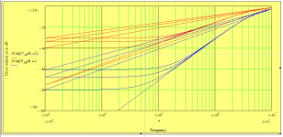
See for example the attached.
Look at the blue lines, and disregard the straight ones (these are 'fly-back lines' because I haven't set up MathCad to suppress them, just installed it).
There is one blue line that goes straight down to the left and crosses -100dB at around 20kHz. That is the EC supression when the EC gain is exactly 1.00000000 and the EC -3dB BW is 20MHz. The EC continues down to infinity at DC.
If the EC is 'just' 1.0001 or 0.9999 it will be limited to a maximum of 80dB reduction (1/10000). With 1.001, the limit is 60dB; with 0.99 it's 40dB. These accuracy limits are shown by the levelling off of the reduction.
(The red lines are similar for 1% accuracy).
So, with an accuracy of the EC of 0.1% and a -3dB bandwidth of the EC circuitry of 1000 x 20kHz = 20MHz, you can suppress distortion in the full audio band by 60dB. I would posit that this is NOT trivial. And 150dB supression is completely pie-in-the-sky.
Jan
Attachments
Last edited:
But as I said my circuit doesn't work like that at all. I specifically designed it with the idea of avoiding the need for matched parts.
Just add -85db to any amp, ignoring the noise floor issue.
I think we've been trying to say that it doesn't work that way. This kind of superposition when dealing with a non-linear system inside a feedback loop does not apply. You need to actually measure the result. Auto-correlation would only remove the noise of the DM (and you would need two of them). I would recommend a lock-in amplifier tuned to each harmonic as possibly useful too.
But as I said my circuit work like that at all. I specifically designed it with the idea of avoiding the need for matched parts.
You need to 'match' the EC gain to the amp CL gain. EC works always with some kind of cancellation or subtraction. That process must be very precise.
If it doesn't work like that it is ordinary negative feedback.
Can you not disclose some conceptual thing about your EC? Or maybe stop wasting your time here and fix your DM ;-)
Jan
- Status
- Not open for further replies.
- Home
- Source & Line
- Analog Line Level
- -290 dB Distortion?