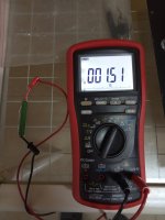
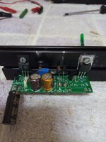
2R61
With this value the max. current about 0.5A !!!
Use 1R.
My usual process with installing Rod's regs:
1. Fit the right resistor into the reg for the current needed e.g. 1A for a 26
2. Test the reg directly on the filaments of the tube in question using a bench supply
3. Adjust the trimmer for the right voltage across the filament, e.g. 1.5V for a 26
4. Install the reg into the chassis with the resistor used for filament bias and the rest of the circuit
5. Measure the supply voltage with the tube in the socket
6. Measure the voltage across the filaments and adjust correctly e.g. 1.5V for a 26
7. Measure the voltage from the positive output of the reg to ground.
8. Compare this voltage with the supply voltage and make sure the headroom is above the minimum specified by Rod and below the max.
9. If the headroom voltage is below the minimum or above max, adjust the cathode resistor or the filament supply (e.g the dropper resistor)
10. You should end up close to the headroom recommended by Rod for the reg, generally around half way between min. and max.
Last edited:
Andy's method is good for setting up filament bias.
Some notes:
Step 2. I prefer to use a dummy load (test resistor) rather than the filament, when the regulator is newly assembled and has not been tested.
For a 26, use 1.5R 7W for testing.
"White coffin" power resistors are cheap! Stock up when you buy other parts at TME, Farnell, Mouser...
Some notes:
Step 2. I prefer to use a dummy load (test resistor) rather than the filament, when the regulator is newly assembled and has not been tested.
For a 26, use 1.5R 7W for testing.
"White coffin" power resistors are cheap! Stock up when you buy other parts at TME, Farnell, Mouser...
OK please power ON the filament supply.
Measure voltage across
1. the input
2. the output
3. across R1
4. across R5
Adjust the pot RV1. Does the voltage across R5 change?
Measure voltage across
1. the input
2. the output
3. across R1
4. across R5
Adjust the pot RV1. Does the voltage across R5 change?
Andy's method is good for setting up filament bias.
Some notes:
Step 2. I prefer to use a dummy load (test resistor) rather than the filament, when the regulator is newly assembled and has not been tested.
For a 26, use 1.5R 7W for testing.
"White coffin" power resistors are cheap! Stock up when you buy other parts at TME, Farnell, Mouser...
Yes - I should probably do that first for safety's sake. But I measure with the actual tube because all tubes are different and my bench supply shows the current going through the tube for the correct voltage, e.g. 1.5V for a 26. The current may be under or over 1A depending on the tube, so I'm also testing the tube out for matching purposes. I do always mark the tube with its socket placement. The resistor is an idealised measurement.
Done!OK please power ON the filament supply.
Measure voltage across
1. the input 14.50
2. the output 1.20
3. across R1 0.93
4. across R5 0.33
Adjust the pot RV1. Does the voltage across R5 change? Yes but only goes down doesn't goes up
OK, now please connect DMM -ve [black] to supply -ve.
connect DMM red to -
R8 left, then right
R9 left, then right
connect DMM red to -
R8 left, then right
R9 left, then right
With this information, the regulator looks to be working fine.
The problem seems to be the high value of R1.
The R1 supplied with the kit (1.0Ω 5W) is a wirewound, and I can't think of any way it could increase to 2.5Ω, unless it has mechanical damage. It is a mystery.
Please change it for a new one. It is easy to buy LONG 5W or 7W wirewound resistors (body length up to 48mm). The long R1 resistors mount on the pad near the input connector, and the R1 right-side pad. You can see it in the PCB foil.
I desoldered and measured 500R so is going on OK but reg. still don't reach the 1.5V across the 1R5 dummy load.
Used the two paralleled 2R resistor at R1 to have 1R.
Used the two paralleled 2R resistor at R1 to have 1R.
Attachments
Last edited:
Rod finally the reg is working ok, I had to slow down R1 to 0R8 to reach the 1.5V into the dummy load.
Now it's time to connect the tube & measure again if all is OK.
Now it's time to connect the tube & measure again if all is OK.
- Home
- Amplifiers
- Tubes / Valves
- 26 preamp Rod Coleman V8 problem


