Looks good. 136V on plate, 9.59V on cathode is basically the same working point as per Andy's schem (138 and 10).
Yea but where does 29 mA current go?
http://www.r-type.org/pdfs/26-1.pdf
137V plate
0V across grid stopper
9,86V cathode positive to ground
Exact values for both channels? So what voltage do you now have over each 4k75?
Iko I don't have connected the 100R before the OPT, do you want that I connect to see if the voltage drop is 0,5-01V? also I don't have connect the 100nF input cap, is necessary?
137V plate
0V across grid stopper
9,86V cathode positive to ground
Exact values for both channels? So what voltage do you now have over each 4k75?
Right channel
137V plate
0V across grid stopper
9,86V cathode positive to ground
over 4k75 64,4V
Left
125V plate
0V across grid stopper
9,47V cathode positive to ground
over 4k75 73,4V
Last edited:
Iko I don't have connected the 100R before the OPT, do you want that I connect to see if the voltage drop is 0,5-01V? also I don't have connect the 100nF input cap, is necessary?
It helps you measure/monitor the current through the tube very easily. While you're debugging your project, I recommend that you do it, just to make sure you have the right bias on the tube.
It helps you measure/monitor the current through the tube very easily. While you're debugging your project, I recommend that you do it, just to make sure you have the right bias on the tube.
OK I will do
over each 4k75?
Right channel
137V plate
0V across grid stopper
9,86V cathode positive to ground
over 4k75 64,4V
Left
125V plate
0V across grid stopper
9,47V cathode positive to ground
over 4k75 73,4V
now you can read it
Ok, we're at 13-15 mA so there is something about the bias. It should be 5,5 mA at 135 V B+ when grid is 10 V below cathode. Try go down to 3k3 istead of 4k75
And, just to be sure, measure voltage between grid pin and cathode pin (the one with the 10R on)
And, just to be sure, measure voltage between grid pin and cathode pin (the one with the 10R on)
Last edited:
It helps you measure/monitor the current through the tube very easily. While you're debugging your project, I recommend that you do it, just to make sure you have the right bias on the tube.
Right channel
Across 100R 1,372V
Left channel
Across 100R 1,544V
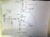
When you come back, could you draw a picture like I did, exactly with the circuit that you have, and with all voltages that you measure on it? One channel only.
What's the voltage on the grid, with respect to ground? Should be 0V.
Left channel
+0,442V
Right channel
+0,448V
- Home
- Amplifiers
- Tubes / Valves
- #26 pre amp