What are you guys using for a V+ supply?
500VA per channel, 4320 rectification, CRCRC. Tried briefly a cap multiplier and although it wasn't exactly horrible it was clearly a step down sonically. No big surprise.
I'll use 300VA toroid and LT4320 rectifier and CRC, Denoiser 317 for polaization and 35V shunt Salas for Aksa Lender.
......You may not get the maximum power output though as the peak to peak output voltage at onset of clipping cannot be higher than the supply voltage.
.......
Yes, it can. The magic of inductive loads. The simulator knows this too 🙂
Yes, I understand that with choke loading, larger voltage swing can occur.
What I said was the "output voltage at onset of clipping", when the output signal is symmetrical and on the verge of going asymmetrical. My understanding is that the output voltage can go higher, but the output signal is then no longer symmetrical, resulting in high total harmonic distortion with large amounts of higher order harmonics. This is a situation that I would want to avoid. The part about "may not get maximum power output" is that the low V+ would not take advantage of the high power capability of the Tokin.
However I did not explain that.
I am an amateur doing diy and learning on my own, so I may have misunderstood the concept of choke loading if my statement is not correct. 😕 🙂
34v p-p with a 25v supply. 35W in 4ohms @ 1.33% thd. For some reason the model i use indicates a much higher distortion than an actual THS51 on the bench but to be honest i have not measured this particular setup, due to the lack of a 5A capable choke.
Otoh, as already mentioned, a speaker choke of 10mH will be perfect in a bi/tri amping setup and this is inevitably forthcoming 🙂
Otoh, as already mentioned, a speaker choke of 10mH will be perfect in a bi/tri amping setup and this is inevitably forthcoming 🙂
Attachments

Is that still considered a follower when the speaker is connected to the source and drain?
What I had said was based on the speaker returning to ground.
What I had said was based on the speaker returning to ground.
The two speaker returns produce identical results in the simulator if the PS has zero impedance and no ripple. As it usually does. In a physical implementation there are differences.
The output path S-D is connected to the earth via an infinitely small resistance via the power supply ...
and hence is parallel to the source choke.
In practice however there are differences. The trick is well known in tube land. The power supply residues might be less this way. And the HF effect could be quite noticeable, hard to simulate though methinks.
and hence is parallel to the source choke.
In practice however there are differences. The trick is well known in tube land. The power supply residues might be less this way. And the HF effect could be quite noticeable, hard to simulate though methinks.
34v p-p with a 25v supply. 35W in 4ohms @ 1.33% thd. For some reason the model i use indicates a much higher distortion than an actual THS51 on the bench but to be honest i have not measured this particular setup, due to the lack of a 5A capable choke.
Otoh, as already mentioned, a speaker choke of 10mH will be perfect in a bi/tri amping setup and this is inevitably forthcoming 🙂
I don't think I would connect the output of the circuit to speakers as it appears to have a 25VDC offset. Or is that a simulation issue and does not happen in real life?
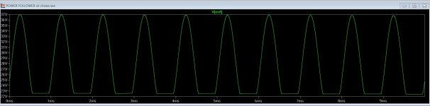
The high THD that your simulation showed was due to clipping. I copied your model and simulated it and the output waveform showed a flattened bottom when zoomed in.
I also did some runs at lesser input/output voltages and although the waveform was not chopped off, the waveform was asymmetrical with the bottom compressed. The distortion profiles also showed large amounts of higher order harmonics, a sign of asymmetric non-sinusoidal output. As far as I can tell, the asymmetry started at peak to peak output voltage greater than 25V, but I may be wrong.
My simulations of the same circuit with the speaker return to ground gave the same peak to peak output voltages, except with so DC offset. So the AC output waveform was the same, as expected.
when done properly, speaker return can go both ways- to "real" or to virtual GND ( other rail than GND)
reason and result is lesser ripple seen across speaker
drawback is live voltage at that speaker connector
reason and result is lesser ripple seen across speaker
drawback is live voltage at that speaker connector
The light bulb just turned and I see the light.
The LTSpice output is relative to ground, but the speaker sees the 25V at both terminals so there is no DC current or DC voltage drop at the speaker.
The LTSpice output is relative to ground, but the speaker sees the 25V at both terminals so there is no DC current or DC voltage drop at the speaker.
hard to simulate though methinks.
Some bits are easy. Add ripple to the ps and observe the amount of ripple passed to the speaker.
As far as I can tell, the asymmetry started at peak to peak output voltage greater than 25V
Perhaps, but so what? You get extra headroom with a little more distortion. It's for free 🙂
I have no problem with distortion. I like distortion too.
I was trying to understand what was happening. I admit to being a diyer with no electronics education, but I try to learn a bit every day and hopeful get some understand of how things work.
I was trying to understand what was happening. I admit to being a diyer with no electronics education, but I try to learn a bit every day and hopeful get some understand of how things work.
I meant the headroom was for free, not the distortion 🙂
Under ideal conditions an inductive load can double the available voltage span of a stage.
Under ideal conditions an inductive load can double the available voltage span of a stage.
But components are not ideal in real life. So the practical acceptable output signal voltage is somewhere in between, depending on the inductor, the Iq, and also on the listener's tolerance of distortion.
In general, it still seems to me that if higher output voltage is desired, higher Vds is advantageous.
It's been a great discussion, as it's been a learning experience.🙂
In general, it still seems to me that if higher output voltage is desired, higher Vds is advantageous.
It's been a great discussion, as it's been a learning experience.🙂
34v p-p with a 25v supply....
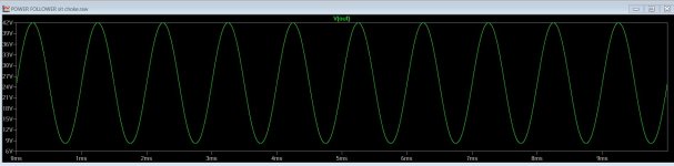
22.8V peak, 45.24V peak to peak, on 24V supply, 0.4% THD, mostly top-clipping.
Attachments
Can I just confirm that the Tokin TH-51S is a straight drop in for the 2SK180 in this schematic from post #109? Would just like to understand my options.
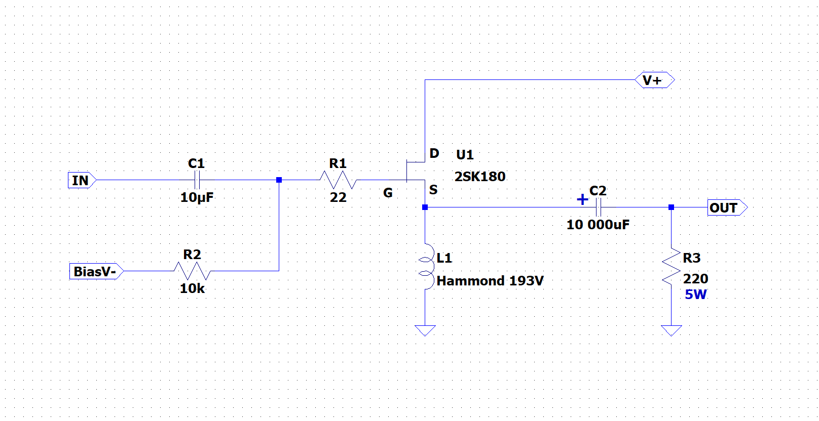
I appreciate I may need to tweak the operating points.
I appreciate I may need to tweak the operating points.
yes
all are depletion* devices, similar power, similar transfer characteristic
*if you are familiar with triodes- same nature as them, regarding biasing - normally fully open, you need to apply negative voltage at gate/grid (ref. to source/cathode) to decrease and control their conductivity/internal impedance
not same circuit, but you can observe graphs and whatnot in SInging Bush thread,, banging your head on graphs showing differences between 3 ( THF51, 2SK182, 2SK180) of them
I'm still banging my head on these graphs 🙂
- Home
- Amplifiers
- Pass Labs
- 25W Single Ended Hammond 193V Choke Loaded 2SK180 L'Amp