With Q3 and Q4 current biased like that, I wouldn't expect DC offset to be very stable. The cascodes will reduce self-heating of Q3 and Q4, but can't help with ambient temperature changes etc.
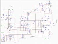
The circuit below may be useful (or at least of interest). It's intended to replace the middle part of your circuit (Q1, Q3, Q4, M1 and M2). M3 and M4 are the same as in your circuit.
How it works is interesting: The DC current I1 through R4 and R5 is always exactly equal to the DC current I2 through R6 and R7 (because there's nowhere else for the current to go), so the output is always biased exactly half-way between the supply rail voltages.
Now what happens if the current gain of Q1 is double the current gain of Q2? The base currents have to be the same, so the current flowing through Q1 and Q4 will be half of the current flowing through Q2 and Q3.
Input impedance is very high, so you should get good linearity from the CCS loaded triode.
Yours shown above is a very good input stage for a hybrid. The high input impedance allows a very linear triode performance, its as if listening to just the tube's intrinsic sound. Could use a 6E5P common cathode or other highly linear valve and get low distortion without gnb. I have used a similar buffer input for a headamp:
An externally hosted image should be here but it was not working when we last tested it.
One issue is that the high input impedance can cause dc leak input issues (use a tightly regulated B+.) But I think the topoology will eventually be part of the "ideal" OPT iron replacement those of us who dabble in hybrid amplifiers desire. I separated the input transistor pairs with 10R and used a current conveyor to bias and allow DC coupling to the output stage, but it was inflexible and I couldn't scale up to higher power. I think your proposal is better for stability.
I am not familiar with the mofset bias/driver scheme you show. What mosfet would you recommend? Due they add significant distortion to the buffer?
Also why the huge coupling caps on the signal lines? Could these be reduced or replaced with led/diodes if the final p-p output were lateral mosfets? Also how would you propose DC-offset adjustment or servoing with this ?
Thanks
Last edited:
Member
Joined 2009
Paid Member
I also was thinking about hybrids in the past, my thoughts are in this thread (not sure how helpful but just in case...)
http://www.diyaudio.com/forums/tubes-valves/174889-cellini-2-hybrid.html
I didn't build anything yet, but the parts are in my basement so it's only a matter of time")
http://www.diyaudio.com/forums/tubes-valves/174889-cellini-2-hybrid.html
I didn't build anything yet, but the parts are in my basement so it's only a matter of time
Last edited:
I also was thinking about hybrids in the past, my thoughts are in this thread (not sure how helpful but just in case...)
http://www.diyaudio.com/forums/tubes-valves/174889-cellini-2-hybrid.html
I didn't build anything yet, but the parts are in my basement so it's only a matter of time
Hi Bigun
Nice to see you around here.
Your circuit looks interesting, when you have time, can you put more detail to make a simulation?
It is old
But I have test and let play this one, a double mustage hybrid amp, without any follower on the tube side, that is why I use a 2 mu tube driver.
it did play, and it was the most musical I had, still have by the way..
regards
But I have test and let play this one, a double mustage hybrid amp, without any follower on the tube side, that is why I use a 2 mu tube driver.
it did play, and it was the most musical I had, still have by the way..
regards
Attachments
- Status
- This old topic is closed. If you want to reopen this topic, contact a moderator using the "Report Post" button.