Hi godfrey
In the first schematic there is a 6BQ5/EL84, in the second a 5687 and in the last a 6SL7GT and another 6BQ5/EL84, is a great valve and in triode connection is very very linear.
What's about the bias, do you think with a +/- 40V regulated supply the DC offset could be unstable?
Best regards
Johann
In the first schematic there is a 6BQ5/EL84, in the second a 5687 and in the last a 6SL7GT and another 6BQ5/EL84, is a great valve and in triode connection is very very linear.
What's about the bias, do you think with a +/- 40V regulated supply the DC offset could be unstable?
Best regards
Johann
Last edited:
Interesting!...6BQ5/EL84, is a great valve and in triode connection is very very linear.
I think so, but don't really know. I suppose the only way to find out is to build it.What's about the bias, do you think with a +/- 40V regulated supply the DC offset could be unstable?
p.s. I just figured out the circuit I posted a couple of days ago won't work. Oops.

Interesting use of the MOSFETs. Do you know their tempco?
I think the dominant temp-drift feature is Q1,R8, and R9. R8 being so much larger than R9will amplify Q1's Vbe temp drift. If you find the right combination of those resistors, and place Q1 near the output devices, you should have a well temp-compensated circuit.
A buddy of mine during college days (mid-'90s) built LC-Audio's 'The End'. It is a class-A transistor amp with zero NFB, and he built the cheap version that has no DC servo or short circuit protection. He still uses it. So for more than 15years that heat monster has kept going, never adjusted once. It runs really hot, can't even touch it for more than half a second, and the heatsinks are very large. I think the bias is set up with the same type of Vbe multiplyer you use, but I'm sure the resistors are valued to cancel drift.
Hi godfrey
No problem, thanks for your help
Hi SemperFi
IR MOSFET datasheet don't say anything about tempco.There is a plot of Id vs Vgs that suggest the tempco point is just above 1A.
Q1 is already near the output transistors.
I't seems to me I will must to experiment with bias and thermal behavior.
Thaks for your help.
Johann
Last edited:
This output stage is less complicated, and has proved quite effective.
Silicon Ray made a kit of it, after we had discussion of the same topic.
I didn't design the triode parts of it, which needs slightly lower value
input grid leak resistor (1st sample input pulled itself 1V negative!)
Other than that one resistor fix, and adjustment to nul out DC offset
that might have drifted in shipping. The box was pretty banged up,
but all the stuff inside was bubble wrapped and taped for survival.
I like how it sounds. And impressed several juniors here in our lab
where we test tons of Class D audio products, but almost no-one
had ever heard class A before. Strange but true, they had no idea...
-----
SR posted a full schematic of his kit with suitable values filled in.
For me, I would suggest something in the neighborhood or 0R15
output current sensors, 33R stoppers, 2R2 470u 2R2 bootstrap,
and 10V zener. The input divider has to be tweaked to offset gate
drop of M1, so either R1 or R2 must include a series pot... There
isn't anything wrong with values SR used, I just don't remember
them offhand. My guesses might differ.
My point is that a proven circuit board, and kit, already exists.
Attachments
Last edited:
Member
Joined 2009
Paid Member
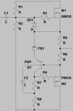
I'm not sure how much experience you have with these things. I don't have much. So I'd choose something relatively simply so it would be easier to construct and de-bug. The attached circuit is my proposal.
The triode is the voltage amplifier. It's anode has a bootstrap type current source which is important here because it will allow the anode to swing above the +ve supply rail (a diode in the supply rail might be a good idea).
I haven't provided much here on how to adjust the dc-offset. My preference would be to use the dreaded capacitor coupled output so that accurate dc-offset is no longer critical since the triode's operating point will drift over time.
You need to consider power-up. The triode will come up slowly, you may get some unwelcome start-up thump.
Attachments
Hi kenpeter
Can you tell me the siliconray's post, I had seen all and couldn't to find the schematics you mention.
Their designs are differents to mine, I use BJTs as output devices.
Thanks.
Hi Bigun
Thanks for help, but my design is zero feedback, add a capacitor like in your design attempt to this. It seems to me that the drift of triode's operating point without a kind of servo are bad news for DC bias offset, this is the reason for separate voltage and current amp with a cap.
Best regards.
Johann
Came on guys, an amp with 0.3% THD at 25W RMS and zero feedback must be at least interesting.
I'm still waiting for help with bias.
Best regards
Johann
It has low distortion and low output impedance only because
of very high amounts of feedback. To assert otherwise is silly.
You ignore strong intrinsic feedbacks from plate and source...
A lack of external components does not imply zero feedback,
but does perhaps contribute to make it interesting...
Came on guys, an amp with 0.3% THD at 25W RMS and zero feedback must be at least interesting.
I'm still waiting for help with bias.
Best regards
Johann
Like I said before, the Vbe multiplier Q1 with R8 and R9 will dominate drift. The combinations of R8 and R9 and temp of Q1 will determine how the whole amp's bias drifts. Offset is harder to say where you must trim, but once trimmed bias drift can make offset drift as well.
Analyze all voltages at 20 and 60 degrees. Thats a delta temp of 40 degrees, and all Vbes will drift by -80mV. My guess is you want R9 twice the size of R8, but havent really done all the math since I aint building it.
Google LC Audio The End, it has an output stage running class-A and no global feedback. Look at how it is biased.
Hi kenpeter
Can you tell me the siliconray's post, I had seen all and couldn't to find the schematics you mention.
Their designs are differents to mine, I use BJTs as output devices.
Thanks.
http://www.diyaudio.com/forums/sili...rid-hifi-amplifier-kit-board.html#post2837030
Anyways, the point was not BJT or MOSFET. This stage can use BJT if the
current of the bootstrap were slightly increased. The point to regard here
is bias. Controlled by a cold transistor's unmultiplied VBE directly across
a pair of easily matched resistors. Rather than by a heated and multipled
VBE minus a pair of dissimilar emitters doing hot work, only then into
the final emitter resistors.
Heated emitters (or sources, or whatever) need to be outside the local
loop that decides bias, else you are always required to guess at temps
and behavior of those emitters with a huge thermal delay.
Hi kenpeter
In audio lenguage zero feedback = no global feedback, if I'm wrong the "Ongaku" can't be named a zero feedback amplifier and there is a cathode follower in its design.
As far as I know MOSFET don't suffer thermal runaway if appropriate heatsink is used, and are easier to biasing.
If memory works, with 2SK175/2SJ55 (elektor 1000W amp) only a trimpot can do the job.
Thanks again
Hi SemperFi
I have seen LC Audio The End when you advised me and the bias is too complex.
IMHO the condition R9 twice the size of R8 isn't a rule, I need 1.25A in output transistors, however I will explore the math.My major concern is biasing cascodes with R10-R14 R11-R15.
Unfortunately I don't know how to make a thermal analysis with LTSpice, I think it will help a lot.
Thanks again
Best regards
Johann
Hi kenpeter
In audio lenguage zero feedback = no global feedback, if I'm wrong the "Ongaku" can't be named a zero feedback amplifier and there is a cathode follower in its design.
As far as I know MOSFET don't suffer thermal runaway if appropriate heatsink is used, and are easier to biasing.
If memory works, with 2SK175/2SJ55 (elektor 1000W amp) only a trimpot can do the job.
Thanks again
Best regards
Johann
Correct: Cathode follower is definitely not zero feedback design.
Sitting on my couch is not zero gravity design. But at the end of
the day, wistful ignorance of complicating fact usually sells best.
Lateral MOSFETs won't run away, other types sometimes do...
But its equally much a sonic problem if your bias shinks away
in the safe direction. Its best not to trust devices that must do
the hottest work to make good decisions about their own bias.
This is especially critical in class B amps. Class A, not so much.
After you run your sim: Alt LeftClick on a component you want
to see the Wattage. While you are holding down ALT and hover
over a schematic symbol, the cursor turns to a thermometer...
Last edited:
I suggest looking at the LME49811 or LME49810 from National Semiconductor - now Texas Instruments. I was designing my own discrete power amp when I stumbled across those ICs. I wasn't able to build a better circuit using discretes... See the LME49811 + STD03 thread for more detail.
Your circuit is basically a solid state amp with a tube preamp. Unless I missed something - which is quite likely. Nothing wrong with that approach, though.
~Tom
Your circuit is basically a solid state amp with a tube preamp. Unless I missed something - which is quite likely. Nothing wrong with that approach, though.
~Tom
Hi kenpeter
LTSpice trick that you mention is already used by me, the thermal analysis that SemperFi suggests is something different if I understood correctly.
Thanks again
Hi tomchr
As far as I know an amplifier has at least two sections: a voltage amplifier and a current amplifier, if you see, the SS stage has unity gain, from this point of view my circuit can't be a SS amp with a tube preamp.
I'm sorry but I hate IC's because of my experience as a TV/Audio repair, you can't imagine how much money I lose by fakes.
Thanks for your advice
Best regards
Johann
LOL. Common sense won't get you far in audio. There are a lot of things that SHOULD work but then, they don't. The empirical world is full of surprises. Not that I have anything against solid theory......just saying.so common sense indicates a hybrid power amp.
You see?I hate the long tailed pair,
Cassiel
Without any encouragement to offend you.
If I say "I accept criticism", is understood to be about my proposed circuit, not about my idiosyncrasy.
Yours is the way to transform a technical issue in a personal matter.
Just now I can understand, I think slowly, you know.
http://www.diyaudio.com/forums/tubes-valves/214817-troubleshooting-big-hum-problem-cj-cav-50-a.html
If, as you confess, you're not tech just a tinkerer, and you don't even know what is a NE555, if you did not have anything valuable to say, I humbly ask that you leave this kind of trolling to the section "The Lounge", there is funny, not here.
- Status
- This old topic is closed. If you want to reopen this topic, contact a moderator using the "Report Post" button.
- Home
- Amplifiers
- Tubes / Valves
- 25W Class A Hybrid Amp