Thanks.Code:
.MODEL ksc3503 NPN
I simulated the circuit using your model of ksc3503, which you posted in #38.
Success!
Now it even works with overdrive/clipping. no latchup
Seems that the model of ksc3503 that one can find on LTwiki is not quite right.
I'll call your model ksc3503_2 to distinguish it from the 'wrong' one.
Attachments

try the kinda-blameless_2.asc file from post #41, this should work.My simulations (based on the .asc file added by catd) are still bad even with the values from the last post#37
or try this one
kinda-blameless_3.asc
Attachments
Both work well!ry the kinda-blameless_2.asc file from post #41, this should work.
or try this one
Thanks!
Now I am in the process of assembling the CelloOne amplifier (from another topic of the lineup)
Maybe this one will be next? Who knows?
That is alright.Thanks.
I simulated the circuit using your model of ksc3503, which you posted in #38.
Success!
Now it even works with overdrive/clipping. no latchup
Seems that the model of ksc3503 that one can find on LTwiki is not quite right.
I'll call your model ksc3503_2 to distinguish it from the 'wrong' one.
I see you have added some compensation.
Between the LTP pair.
Also adjusted the TMC comp.
But if it works it is alright.
I like the fact that you build my amplifiers.Both work well!
Thanks!
Now I am in the process of assembling the CelloOne amplifier (from another topic of the lineup)
Maybe this one will be next? Who knows?
I can hardly believe someone likes my stuff 😀
Hi...
In case I wanted to build this thing, I searched the net for the Exicons (10N20/10P20).
They are not easy to get and then not cheap either.
That's why I tried other Mosfets, which on the one hand are included in the LTSpice database
and on the other hand can also be purchased cheaply from my preferred supplier.
The result was IRFP240/9240.
At least in the simulation below it works with them.
Attachments
@catd
https://gb.profusion.uk/uk/ecx10n20
https://gb.profusion.uk/uk/ecx10p20
I dont think that is expensive.
For using IRFP240/9240 I believe we need a VBEMultiplier in VAS.
Laterals like ECX10N20 are easy to drive, but IRFP240 is not so easy.
And there is the temperature that a VBEMultiplier takes care of. HEXFET can runaway when heated.
But if you try IRFP240 it might be good. I really dont know.
Best is of course the lateral ECX10N20.
Last edited:

That is of course better than IRFP240/9240.I will try 2SK1058/2SJ162
Because it is Laterals.
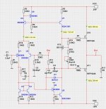
I still have some circuit boards left over from my TO39-AMP project. They are designed from the outset so that they can be used for different amplifier versions in the "blameless topology". I have now considered whether it would be possible to build a MOSFET output stage with them. The circuit is largely predetermined by the existing circuit board, it is actually only possible to change the components or their values. I have also made up my mind not to use lateral MOSFETs. The circuit must therefore be designed in such a way that thermal runaway of the quiescent current of the output transistors used (IRFP240/9240) is avoided. The circuits above with IRFPxxx-transistors show exactly this undesirable behavior.
I simulated the circuit shown below and tried to take the temperature conditions into account.

The following is assumed:
The transistors U5(VAS), U7(CCS), U14 (Bias), U10-13 (end transistors) are on the same heat sink.
Temperatures:
T1: End transistors
T2: CCS/VAS transistors, they are heated by the end transistors and by themselves (around 270mW)
T3: Bias transistor heated by the end transistors
T4: other semiconductor components, heated by the warm air inside the amplifier housing
Since the main heat source is the end transistors, there must be a temperature gradient towards the other transistors, which I have tried to depict using the different temperatures.
The formulas used for this are a rough estimate.
With the given models and component values, the simulation shows a very constant quiescent current at temperatures from 25°C to 125°C (77mA per output transistor, constant)
Distortion THD is in the expected range at max. approx. 0.03% @20000Hz,100Watt
(THD : 0.0012% @1000Hz,100Watt....0.0016% @1000Hz,1Watt)
The LTSpice file is attached. Models included.
I simulated the circuit shown below and tried to take the temperature conditions into account.
The following is assumed:
The transistors U5(VAS), U7(CCS), U14 (Bias), U10-13 (end transistors) are on the same heat sink.
Temperatures:
T1: End transistors
T2: CCS/VAS transistors, they are heated by the end transistors and by themselves (around 270mW)
T3: Bias transistor heated by the end transistors
T4: other semiconductor components, heated by the warm air inside the amplifier housing
Since the main heat source is the end transistors, there must be a temperature gradient towards the other transistors, which I have tried to depict using the different temperatures.
The formulas used for this are a rough estimate.
With the given models and component values, the simulation shows a very constant quiescent current at temperatures from 25°C to 125°C (77mA per output transistor, constant)
Distortion THD is in the expected range at max. approx. 0.03% @20000Hz,100Watt
(THD : 0.0012% @1000Hz,100Watt....0.0016% @1000Hz,1Watt)
The LTSpice file is attached. Models included.
Attachments
Last edited:
No comments?
Then I'll comment myself...🙂
I've since found and tried out other models (by Ian Hegglund) for the Mosfets.
With these you have to tweak the resistors P1 and R26 (Bias) a bit, but the result is quite the same.
Then I'll comment myself...🙂
I've since found and tried out other models (by Ian Hegglund) for the Mosfets.
With these you have to tweak the resistors P1 and R26 (Bias) a bit, but the result is quite the same.
- Home
- Amplifiers
- Solid State
- 25 Watt Kinda Blameless with TMC, fast amplifier