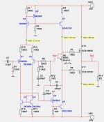
I changed C2 from 22pF to 68pF.
Now the overshot should be gone.
Bandwidth is now like 1.5 MHz.
What can be done about the clipping behavior?
Now the overshot should be gone.
Bandwidth is now like 1.5 MHz.
What can be done about the clipping behavior?
Attachments
Last edited:
What about this? This phenomenon seems extremely dangerous to meBut there is also very bad clipping behavior in case of overload, e.g. with input sine 1.4 Vpp, see attached picture.
Seems the output went to constant voltage
Imagine a source with a high level and suddenly we get about -18V DC voltage at the amplifier output....
The speaker goes up in smoke....
catd - thanx for sharing .asc file
Attachments

?
To compare this correctly with the @lineup-circuit, you should disable RI, CI. (Then it gets worse).C2=68pF Square wave 20kHz....
To reach the same result as with RI,CI, but only by increasing C2,
C2 must be min. 100p.
This then increases THD by an order of magnitude,
while THD is decreased when using RI,CI.
I don't really know what's going on there. ?Seems @lineup hasn't simulated this?What about this? This phenomenon seems extremely dangerous to me
Is it a "special feature" of LTSpice? can't imagine this....
@lineup
I've listed the models I used below so you can compare them with yours.
BJT models come from the LTwiki.
Mosfet models are from Ian Heglun and were posted a few days ago in another thread you may have seen. There are other models of the same mosfets in the same post mentioned, but for them LTSpice reports an error with curly brackets...
.model 2N3906 PNP(IS=1E-14 VAF=100 BF=200 IKF=0.4 XTB=1.5 BR=4 CJC=4.5E-12 CJE=10E-12 RB=20 RC=0.1 RE=0.1 TR=250E-9 TF=350E-12 ITF=1 VTF=2 XTF=3 Vceo=40 Icrating=200m mfg=NXP)
.model 2N3904 NPN(IS=1E-14 VAF=100 Bf=300 IKF=0.4 XTB=1.5 BR=4 CJC=4E-12 CJE=8E-12 RB=20 RC=0.1 RE=0.1 TR=250E-9 TF=350E-12 ITF=1 VTF=2 XTF=3 Vceo=40 Icrating=200m mfg=NXP)
.MODEL KSA1381 pnp IS=5.5544E-14 BF=148 BR=1.592 ISE=2.0546f NE=1.5 ISC=3.24807E-10 NC=2 VAF=580 VAR=100 IKF=0.2163 IKR=0.087544 RB=10.18 RE=0.0512 RC=4.072 CJE=9.572p VJE=0.748 MJE=0.371 FC=0.5 CJC=1.147p VJC=0.541 MJC=0.329 TF=1.0312E-09 XTB=0.907 EG=0.62 XTI=3
.MODEL KSC3503 NPN IS=2.0893E-14 BF=101.5 NF=1 BR=7.655 NR=1.007 ISE=4.3652E-14 NE=1.5 ISC=1.2598n NC=2 VAF=717.25 VAR=13.16 IKF=0.2512 IKR=0.0832 RB=2.98 RBM=0.001 IRB=0.001 RE=0.5305 RC=0.9 QCO=0.05 RCO=50.1187 VO=2.476 GAMMA=1.8231E-7 CJE=6.6039E-11 VJE=0.7017 MJE=0.3253 FC=0.5 CJC=6.6072p VJC=0.5 MJC=0.2439 XCJC=0.6488 XTB=1.4089 EG=1.2129 XTI=3 Vceo=300 Icrating=100m mfg=Fairchild
.model 10N20-75C VDMOS (Rg=60 Vto=0.09 Lambda=3m Rs=0.277 Kp=0.92 Rd=0.7 Ksubthres=0.11 Mtriode=0.3 Cgdmax=100p Cgdmin=5p a=0.25 Cgs=600p Cjo=1100p m=0.7 VJ=2.5 IS=4.0E-6 N=2.4 mfg=IH150521)
.model 10P20-75C VDMOS (pchan Rg=60 Vto=-0.45 Lambda=5m Rs=0.432 Kp=0.745 Rd=0.2 Ksubthres=0.14 Mtriode=0.4 Cgdmax=100p Cgdmin=5p a=0.25 Cgs=600p Cjo=1100p m=0.7 VJ=2.5 IS=4.0E-6 N=2.4 mfg=IH150521)
I did a lot of different simulations in LTspice I haven't seen a case like this before...Very strangeI don't really know what's going on there. ?Seems @lineup hasn't simulated this?
Is it a "special feature" of LTSpice? can't imagine this....
I will try with C2=100pFTo compare this correctly with the @lineup-circuit, you should disable RI, CI. (Then it gets worse).
To reach the same result as with RI,CI, but only by increasing C2,
C2 must be min. 100p.
This then increases THD by an order of magnitude,
while THD is decreased when using RI,CI.
I don't really know what's going on there. ?Seems @lineup hasn't simulated this?
Is it a "special feature" of LTSpice? can't imagine this....
@lineup
I've listed the models I used below so you can compare them with yours.
BJT models come from the LTwiki.
Mosfet models are from Ian Heglun and were posted a few days ago in another thread you may have seen. There are other models of the same mosfets in the same post mentioned, but for them LTSpice reports an error with curly brackets...
.model 2N3906 PNP(IS=1E-14 VAF=100 BF=200 IKF=0.4 XTB=1.5 BR=4 CJC=4.5E-12 CJE=10E-12 RB=20 RC=0.1 RE=0.1 TR=250E-9 TF=350E-12 ITF=1 VTF=2 XTF=3 Vceo=40 Icrating=200m mfg=NXP)
.model 2N3904 NPN(IS=1E-14 VAF=100 Bf=300 IKF=0.4 XTB=1.5 BR=4 CJC=4E-12 CJE=8E-12 RB=20 RC=0.1 RE=0.1 TR=250E-9 TF=350E-12 ITF=1 VTF=2 XTF=3 Vceo=40 Icrating=200m mfg=NXP)
.MODEL KSA1381 pnp IS=5.5544E-14 BF=148 BR=1.592 ISE=2.0546f NE=1.5 ISC=3.24807E-10 NC=2 VAF=580 VAR=100 IKF=0.2163 IKR=0.087544 RB=10.18 RE=0.0512 RC=4.072 CJE=9.572p VJE=0.748 MJE=0.371 FC=0.5 CJC=1.147p VJC=0.541 MJC=0.329 TF=1.0312E-09 XTB=0.907 EG=0.62 XTI=3
.MODEL KSC3503 NPN IS=2.0893E-14 BF=101.5 NF=1 BR=7.655 NR=1.007 ISE=4.3652E-14 NE=1.5 ISC=1.2598n NC=2 VAF=717.25 VAR=13.16 IKF=0.2512 IKR=0.0832 RB=2.98 RBM=0.001 IRB=0.001 RE=0.5305 RC=0.9 QCO=0.05 RCO=50.1187 VO=2.476 GAMMA=1.8231E-7 CJE=6.6039E-11 VJE=0.7017 MJE=0.3253 FC=0.5 CJC=6.6072p VJC=0.5 MJC=0.2439 XCJC=0.6488 XTB=1.4089 EG=1.2129 XTI=3 Vceo=300 Icrating=100m mfg=Fairchild
.model 10N20-75C VDMOS (Rg=60 Vto=0.09 Lambda=3m Rs=0.277 Kp=0.92 Rd=0.7 Ksubthres=0.11 Mtriode=0.3 Cgdmax=100p Cgdmin=5p a=0.25 Cgs=600p Cjo=1100p m=0.7 VJ=2.5 IS=4.0E-6 N=2.4 mfg=IH150521)
.model 10P20-75C VDMOS (pchan Rg=60 Vto=-0.45 Lambda=5m Rs=0.432 Kp=0.745 Rd=0.2 Ksubthres=0.14 Mtriode=0.4 Cgdmax=100p Cgdmin=5p a=0.25 Cgs=600p Cjo=1100p m=0.7 VJ=2.5 IS=4.0E-6 N=2.4 mfg=IH150521)
But my squarewave doesnt indicate a problem with 68pF
I will input those MOSFET models. Hope they work.
Does your simulation see if the anti clipping diode work?
MOSFET models do not work.
There is not somthing called VDMOS in Multisim.
I tried with NMOS but this did not work either.
Actually the squarewave is perfect with 47pF for C2.
How come you see a problem?
There is not somthing called VDMOS in Multisim.
I tried with NMOS but this did not work either.
Actually the squarewave is perfect with 47pF for C2.
How come you see a problem?
Last edited:
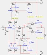
where did you add it?I added an anti clipping diode.
and why did they add it?
your U6 is “going crazy” from the signal, it needs a resistor in the collector and increase the current to him

This is circuit I have to trust in. Because it simulates very well in my software.where did you add it?
and why did they add it?
your U6 is “going crazy” from the signal, it needs a resistor in the collector and increase the current to him
Here you can see the anti clipping diode. It is also in @catd circuit.
Last edited:
Code:
.MODEL ksc3503  NPN
+ IS=3.510E-14            BF=174.09             VAF=600
+ IKF=0.12325             ISE=2.2538E-13        NE=2.0
+ BR=0.64499              VAR=100               IKR=0.43102
+ ISC=6.4644E-10          NC=1.5                RE=0.048
+ RC=0.815                RB=8.134              RBM=0.034
+ IRB=3.0e-6              CJE=8.10E-12          MJE=0.401
+ VJE=0.75                CJC=8.20E-12          MJC=0.31
+ VJC=0.75                TF=9.995E-10          XTF=2
+ VTF=35                  ITF=1                 TR=1.0E-8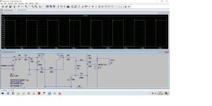
+ EG=0.84 XTB=2.5 FC=0.5My simulations (based on the .asc file added by catd) are still bad even with the values from the last post#37
I don't understand why. In the topic of the Cello amplifier, the results between LTspice and Multisim were very similar Where is the problem?
I don't understand why. In the topic of the Cello amplifier, the results between LTspice and Multisim were very similar Where is the problem?
Название темы не соответствует необходимости установки дополнительных пассивных нелинейных элементов. Артефактное исследование)))).
This design should have become single-stage long ago....
I see the topology of the circuit of the last century and I want to cry... 😢This is circuit I have to trust in.
This design should have become single-stage long ago....
- Home
- Amplifiers
- Solid State
- 25 Watt Kinda Blameless with TMC, fast amplifier