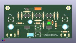
Kinda Blameless amplifier with TMC.
Bandwidth: >6 MHz
Distortion: THD 0.00006% (if we should believe simulation 😀 )

Bandwidth: >6 MHz
Distortion: THD 0.00006% (if we should believe simulation 😀 )

I really like your threads @lineup, but could you not partner up with a local fellownerd who could build a few iterations before posting schematics? Im following sooo many interesting ampliers threads, and already feel diyaudio is almost poluted with so many, that its getting hard to decide for people what to build. Threads getting so long because initial simulations get so much critzisism for not working or living up to promises. Sometimes justifiably. Sometimes not.
If at least real life measurements for version 0.1a were published, it would save so much of peoples time, and save us from a lot of negative fruitless discussions.
Its just my thoughts, and maybe they are very far from how most members would like the forum to be.
Cheers!
If at least real life measurements for version 0.1a were published, it would save so much of peoples time, and save us from a lot of negative fruitless discussions.
Its just my thoughts, and maybe they are very far from how most members would like the forum to be.
Cheers!
H
HAYK
Post in thread 'Ultra Amplifier with JFET input and Lateral MOSFET out' https://www.diyaudio.com/community/...ut-and-lateral-mosfet-out.409798/post-7614188
Try with these models for more realistic results.
Try with these models for more realistic results.
I'd like to build amplifiers, but I can not.
Because is no place in my little room.
I leave it to the diyadio people to build.
If they like.
I am sure my amplifiers will work well. Otherwise I do not post them.
And I am not the only one posting without building.
🙂
Because is no place in my little room.
I leave it to the diyadio people to build.
If they like.
I am sure my amplifiers will work well. Otherwise I do not post them.
And I am not the only one posting without building.
🙂
I have tried those models.Post in thread 'Ultra Amplifier with JFET input and Lateral MOSFET out' https://www.diyaudio.com/community/...ut-and-lateral-mosfet-out.409798/post-7614188
Try with these models for more realistic results.
Unfortunately they did not work in Multisim 🙁
Quick and dirty layout for prototyping. Have fun with it.
U=Q
Input Cap: 2u2 ECW-FD2W225K4
Feedback Cap: 100uF ECE-A1AN101X
Decoupling: 100uF/35V Rubycon RX30 or other 8mm/3.5mm
C2/C4 with 5mm pitch
Terminals are 8191
PCB size 100x50mm
U=Q
Input Cap: 2u2 ECW-FD2W225K4
Feedback Cap: 100uF ECE-A1AN101X
Decoupling: 100uF/35V Rubycon RX30 or other 8mm/3.5mm
C2/C4 with 5mm pitch
Terminals are 8191
PCB size 100x50mm
Attachments
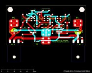
Maybe I'm wrong or I don't see, but there is no connection between J4, R1, R4, C3 (ground side) and GDN...Quick and dirty layout for prototyping. Have fun with it.
U=Q
Input Cap: 2u2 ECW-FD2W225K4
Feedback Cap: 100uF ECE-A1AN101X
Decoupling: 100uF/35V Rubycon RX30 or other 8mm/3.5mm
C2/C4 with 5mm pitch
Terminals are 8191
PCB size 100x50mm
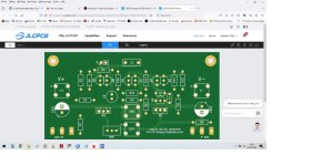
You mean Post#8 is correct.
For me it reads like 12:08.
We are in different timezones .. 😀
For me it reads like 12:08.
We are in different timezones .. 😀
lineup used a broken version I replaced two minutes after posting it. The uploaded version at 11:08AM is correct:
Hello...
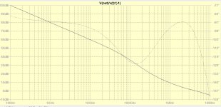
I pasted the circuit from post #1 into LTSpice. (.asc file attached incl. models)

It simulates there quite OK with a normal sine input. (input 1.2Vpp, output 20W, THD=0.0025%, 20kHz)
With square wave it shows massive overshoots.
This could be fixed with an input low pass RI=1K CI=220p.
But there is also very bad clipping behavior in case of overload, e.g. with input sine 1.4 Vpp, see attached picture.
Seems the output went to constant voltage

Did you simulate this in your program? Maybe our models are different.
But I think the circuit still needs some work before transferring it to PCB layout.
I pasted the circuit from post #1 into LTSpice. (.asc file attached incl. models)
It simulates there quite OK with a normal sine input. (input 1.2Vpp, output 20W, THD=0.0025%, 20kHz)
With square wave it shows massive overshoots.
This could be fixed with an input low pass RI=1K CI=220p.
But there is also very bad clipping behavior in case of overload, e.g. with input sine 1.4 Vpp, see attached picture.
Seems the output went to constant voltage
Did you simulate this in your program? Maybe our models are different.
But I think the circuit still needs some work before transferring it to PCB layout.
Attachments
Last edited:
I have great doubts that this will work well, the sound is still far away.I am sure my amplifiers will work well.
A simple example from the diagram in the first post: look at the C2 C4 circuit with a “slave link” via R12, what coefficients did you use for linear approximation of compensation and what type? The answer is simple - they are not there, and it is also impossible to establish the type. The coefficients you select are not used in audio as they affect the stability of the system as a whole.
The second point is the u6 transistor, which will “stick to the current” if there is a clip in the audio signal.
It is best to measure distortion not at the output of the amplifier, but at the output of the first stage and at the input of the output power transistors, since these distortions depend only on the circuit parameters and the NFB only proportionally reduces them. I repeat again, distortions do not disappear, but only decrease in proportion to the depth of the NFB. At the moment of transition through 0 of the power transistors, when the common NFB does not work, all this is transferred to the load and, accordingly, the measured distortions in the model do not correspond to the real ones.
A rough estimate is that the TND distortion in your circuit will be around 2 percent.
I am also surprised by your desire in circuits to control side transistors (Laterals) with current with a nonlinear (expotential dependence) conversion of current into voltage.
Where did you learn this?
- Home
- Amplifiers
- Solid State
- 25 Watt Kinda Blameless with TMC, fast amplifier