That chip need a pos Vin with respect to its output.
In your circuit you connect a neg Vin with respect to its output.
Therefor it cannot possibly work as intended. It does not regulate, but the circuit parts and values just lead to some output voltage that you see.
That the chip somehow survived this reverse polarity suggests some internal protection.
Jan
ebuckley002
Have you seen the application circuit for a high voltage floating regulator on page 26 of the datasheet ?
Have you seen the application circuit for a high voltage floating regulator on page 26 of the datasheet ?
Have you thought about using a uA723 regulator in a floating configuration, the power dissipation through the uA723 will be a non issue, just mount the series pass transistor on a heatsink.
The uA723 also needs a positive supply with respect to it's 'gnd' so you can't just plug that in.
There is a way to use it, and the '3080, in a neg regulator: use it 'upside down', with the Vin terminal towards ground and its 'gnd' terminal towards the negative output rail. The complicating factor is that the control circuitry now must sit between the chip output and the neg output rail.
Nothing special about it, but if you're not used to such mental gymnastics it can be daunting.
The other solution would be to use a '337 as suggested above.
But the simplest solution is using a pos output regular Maida reg, and ground its postive output terminal and use its 'gnd' terminal as neg output. That way you only need one board type, and you end up with two regs that have identical performance.
The only thing to be careful with is that none of the transformer or capacitive terminals are grounded. There's only one ground point and that's the original pos output terminal. That works like a charm and requires no redesign.
Have fun,
Jan
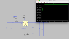
LT3090 may well be oscillating. The datasheet (page 11) states: "Use a minimum output capacitor of 4.7μF with an ESR less than 0.5Ω to prevent oscillations."
BTW the circuit in post #1 definitely cannot work as absolute maximum ratings are exceeded (with respect to GND pin). However circuit in post #20 looks better.
Ii was just pointed out to me that the 3090 is a negative regulator which of course will work fine here. The 3080 will obviously not.
Jan
Jan
The uA723 also needs a positive supply with respect to it's 'gnd' so you can't just plug that in.
Here is the uA723 configured as a floating negative regulator from page 9 of the TI datasheet.
- Home
- Amplifiers
- Power Supplies
- 21st century Maida regulator - negative version