To gurevise:
Does your amplifier show any signs of stress than? Does the 65 mA or 60 mA you mentioned perhaps relate to the current through the 300B? The bias jack on the amplifier is for monitoring the 300B.
Does your amplifier show any signs of stress than? Does the 65 mA or 60 mA you mentioned perhaps relate to the current through the 300B? The bias jack on the amplifier is for monitoring the 300B.
Last edited:
Datasheet shows A2 is a normal use for the 211. Sort of a pain for the driver to go from no grid current to driving grid current though. 833 is about the same as far as needing to transition into grid current.
SpreadSpectrum,
I built the circuit I've got around an output transformer that was not wound for high voltage and the winder asked me not to run it in the KV range. My way of taking care of that is to run it as a grounded grid into A2.
Yeah, I was planning on using a 5k transformer at 110mA and 620V (68W). The transformers I have are built for transmitting tube voltages, but I'm trying to develop a circuit that can get really good performance with transformers that aren't exotic, like, say a standard Edcor 25W SE model.
575 Ohms in 211 cathode seems reasonable.
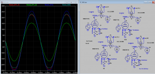
Tube bias -43V
Voltage across tube 917 V. 960 on plate minus cathode bias.
Current 75mA
Plate dissipation 69W. A bit below 75W max spec.
Output power is at 26W before clipping. This is close to what Koons simulation shows.
To PFL200: 300B runs at 400 on pate with 60mA. I don't know what you mean by stress. Like tubes glowing red ?
Last edited:
To gurevise: Yes, like glowing red. But your problem seems to be solved so just forget about my post.
Gave amp with new 211 bias a quick listen yesterday. Seems a bit less relaxed then before. Everything else is the same. I'll let it play for a few days to settle.
Well, if you look at https://frank.pocnet.net/sheets/049/2/211.pdf, you discover all sorts of juicy bits on page one.
1000 VA has an advisory of –61 VG relative to VK, and an operating current of about 58 mA. Close enough.
And there you go. As another poster said, a minimum of 600 Ω. This calculation shows much higher, about 1 kΩ. Using
Yay!
GoatGuy
1000 VA has an advisory of –61 VG relative to VK, and an operating current of about 58 mA. Close enough.
E = I R
61 = 58 ma • R
R = 61 ÷ 0.058 = 1,100 Ω
61 = 58 ma • R
R = 61 ÷ 0.058 = 1,100 Ω
And there you go. As another poster said, a minimum of 600 Ω. This calculation shows much higher, about 1 kΩ. Using
P = I² R
P = 0.058² × 1000
P = 3.36 W
So, having a 5 watt or 10 watt resistor is the right idea. P = 0.058² × 1000
P = 3.36 W
Yay!
GoatGuy
I guess this is the balance between design execution by the text book vs what sounds best. As an engineer I understand design by text book. As an audiophile i struggle to understand why "sound electrical designs" do not sound good. How do you design for wide soundstage or dynamics or open sound. Not sure.
Like I said. Amp puts out about 8W with 1.1k cathode resistor. Not enough.
One more thing. I added in-rush thermistor current limiter SG330 in series with power transformer primary. There was a huge inrush current at turn on to charge huge power capacitances. It was blowing 3A slow blow fuse sometimes.
There is about 0.8V voltage drop across it when amp is on. I don't think it's a problem.
Last edited:
I guess this is the balance between design execution by the text book vs what sounds best. As an engineer I understand design by text book. As an audiophile i struggle to understand why "sound electrical designs" do not sound good. How do you design for wide soundstage or dynamics or open sound. Not sure. . . . . . .
You're not alone. I've often thought it would be great to have a reference thread or list somewhere with correlations people have made between circuit and sound.
It frequently proves to be a contentious topic though. Maybe better for smaller groups and more personal communications between interested folks. At an audio fest or similar is probably the best place.
Hearinspace,
I had the good fortune to attend all of the VSAC's in Silverdale Washington.
I had the opportunity to listen to some real good off-the-cuff discussions by experts,
as well as some real good seminar presentations.
Unfortunately, after a long wait, the very last VSAC was at Vancouver Washington in 2008.
That was a good conference too, but did not have enough momentum to cause any more VSAC's.
Thanks to all who had a hand in producing those conferences.
VSAC (Vacuum tube State of the Art Conference).
Last edited:
To 6A3sUMMER :
Can you share anything / gists from those meetings ? Any electrical design aspects that lead to sound improvements ?
For instance: I looked into Cary 805 output noise. The rectifier diodes switching noise is clearly visible. Not sure which rectifier, as all tubes run of separate DC (rectified) filaments. Plus, 211 and 300B plate supplies may be noisy too. So the questions does it makes sense to try to reduce / eliminate rectifier diodes switching noise ? Would that lead to audible improvements
It probably will but also might not. A very helpful engineer, formerly with Boeing as a noise specialist ( IIRC) was asked how to get rid of hum on an otherwise great sounding amplifier. He offered advice but also suggested that the hum might well have something to do with the pleasing aspect of the sound.
I have been working on a circuit that's been up and running for a few weeks, making improvements with incremental changes. I got it sounding really good to our household's ears with only a little hum from heaters and buzz from imperfect ground relationships left to take care of.
Last night I put a DC bias on the heaters and changed the power supply grounding scheme and got the amps running as close to silent as they're likely to get on a piece of wood. Great clarity and and a perception of deep silence in the spaces - very good, . . . . . yet there's a certain something that got lost and I'm not altogether certain I like the 'improvement'.
You might enjoy looking at this thread. I'm not a hundred percent sure but I think it was also Mark Johnson who posted a list of rectifiers (maybe even in that thread) with some noise data and suggested circuit values that would go most of the way to snubbing them without having to do use his bell ringer. Also lots of other stuff on rectifier noise in the forums.
- Home
- Amplifiers
- Tubes / Valves
- 211 question