Gents,
I have 211 in my Cary 805 amp (SE amp). It runs in self bias mode with 375 ohms cathode resistor. Tube current is 105 mA with 1000 volts on the plate and -40v bias. Not sure why current is so way off. It suppose to run at about 65mA. 211 tubes in both amps run at about same current. Within 5mA from each other.
Not sure if tubes are old and drifted this much.
I can adjust cathode R to lower current or get new tubes.
I don't have any experience with 211 tubes or 211 tester. Let me know what you think.
Thanks
Sergy
Current is way off because the operating point is wrong; with 375 ohms cathode resistor the tube will behave as you measured.
But 1000 volts on the plate with 105 mA is well beyond maximum plate dissipation of a 211 triode.
You cannot just replace an 805 with 211 without changing the cathode resistor.
Make the cathode resistor at least 600 ohms (preferably a 10 watt resistor because it will get hot) which would give a more normal operating point, and measure again.
Last edited:
Does it say that it is supposed to run at 65 mA in the manual? If not, where does it come from than?
Does your version has a switch to select either 805 or 211?
Does your version has a switch to select either 805 or 211?
The 805 is the model number. The amp is made to run either 211 or 845 at 100 Watts dissipation. So, according to that, you're only 5mA over. But Cary claims the 211 is a 100 Watt dissipation tube , which isn't in agreement with the RCA data sheet. Not that you're not allowed , you can run it up there if you want but , theoretically at very least, the tube will not last as long at that dissipation as it will somewhat lower.
According to the RCA data sheet, to run right at max recommended dissipation with 1000V on the plate you would bring the current down to 75mA.
If you know how to draw a load line you could decide what looks best with 1000V on the plate , loaded with an 8KΩ Output Transformer Primary,( which is what the Cary uses ) and set the current there, or just do it by ear, settling on what you like the sound of best.
All this is said thinking in terms of western made 211 tubes. I have no idea what the Chinese made tubes will bear.
Attachments

The 211 and 845 are quite different.
With the same plate voltage, they require different bias voltage to get the same current (different 'cathode' [filament] self bias resistors).
Go from there.
If the amplifier does not have negative feedback, and uses the same output transformer, then . . .
845 needs more driver voltage, but has lower plate resistance, rp, so better damping factor with 8k load, and better low frequency response.
211 does not need as much driver voltage, but has higher plate resistance, rp, so worse damping factor with 8k load, and not as good low frequency response.
Why is there a 375 ohm cathode resistor? It should be 1125 ohms or something close to that. Did someone modify the amp?
The 805 series has been in production for a number of years. While there are some internal changes in the 805C over the 805B, the biggest difference is the output tube. The B uses a 211 and the C a 845. They both use the same input and driver tubes.
Still another version 805AE, with 211/845 selector switch, so which version do you own?
Still another version 805AE, with 211/845 selector switch, so which version do you own?
Wonder if the amp has mixed bias.
Maybe there is a fault and the fixed bias portion has gone to zero; or is out of adjustment.
Would be odd though for a fault to happen on both channels at the same time.
Maybe there is a fault and the fixed bias portion has gone to zero; or is out of adjustment.
Would be odd though for a fault to happen on both channels at the same time.
Last edited:
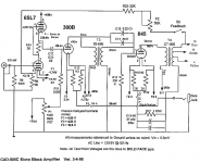
805 schematic
Here a readily available CAD805 schematic:
Hey! A 1125 ohm cathode resistor! Self bias.
And.... 375 x 3 = 1125.... better check the cathode resistor(s); apparently there should be three 375 ohm resistors in series.
Here a readily available CAD805 schematic:
Hey! A 1125 ohm cathode resistor! Self bias.
And.... 375 x 3 = 1125.... better check the cathode resistor(s); apparently there should be three 375 ohm resistors in series.
Attachments
Last edited:
I would not trust that Service Manual.
Check R17 which is the 1125 ohms cathode resistor, decoupled with two parallelled 51 uF capacitors.
According to the parts list, R17 is an 1125 ohms / 0.5 watt resistor.
Well, voltage drop over R17 is 114 V, so DC current is 114/1125 = 101 mA.
114 V with 101 mA is 11.55 watt dissipation, so the 0.5 watt resistor will explode...!
Even the Chinese are not that stupid....
Cary 805C class A SET monoblock amps, v2 Photo #1618884 - UK Audio Mart
Anyone who has seen this snapshot will believe they're lots of misprint happened all the time, no update in sight.. stupid or not is up to you.
Anyone who has seen this snapshot will believe they're lots of misprint happened all the time, no update in sight.. stupid or not is up to you.
Gurevise,
If 375 Ohms is what you have in the cathode then the tubes are not that far off. Perhaps a bit old so needing a smaller grid bias voltage to get the current up there.
A new 211 by the RCA curves would ordinarily want somewhere around 75 - 100 Ohms more for something just above 450Ω cathode R to get 100mA at Vp=1000VDC.
Do they look like they are replacements for the original resistors ? . . . . . Or perhaps the 211's are recent manufacture and bias a bit differently anyway . . . . .
I bought amp second hand. Looks to me that there were some mods done to it.
About 211 bias, Looks like I need to change 375 ohms to something like 1.1k to get current to reasonable 60mA or so.
One thing I discovered. Inter-stage transformer located between 300B and 211 does not have by pass 2uF capacitor from primary to secondary as shown on 805 schematic.
I can install "Solen 2.0uF 700V Silver Sound MKP Silver Metallized Polypropylene Film Capacitor" there.
Not sure how old amp is but it is old. It does not have 211/845 switch. It has 6SL7. Later versions have dual 6SN7
Last edited:
2 caps, 0.22u and 2u, not bypass cap but coupling caps to compensate IT freq. response.
Normally with bias -114/-51V 845/211, they delivered 20 Watts in A1. To deliver 50W, they need to be driven into A2 to get about 30V rms out for 50W output. Not sure what's effect of additional coupling caps as far as blocking effect is concerned, you can try.
OT is 8k, it's better match for 845 than 211, so 211 is likely to get early clipping than 845, together it may have some sonic impact.
Last edited:
It's called a bridging capacitor and GEC used it in a cathode coupled circuit and noted that it prevented oscillation. I've read more recent comments on it being a method for defeating leakage inductance in poorer quality transformers so the HF isn't attenuated. I've also read that at high signal levels you get a jump in level as the capacitor becomes dominant. I have never used it and don't know anything about it myself.
I would call Cary with the serial number and ask them what it is and whether you can get a schematic for it. Maybe that version never had the capacitor.
If you go ahead with changing the cathode resistor remember you're cutting the current almost in half so it might be wise to note the B+ voltage rise.
Attachments
Increased 211 cathode resistor to 1125 ohms. Tube current is at 47mA. Bias is at -52V. Tube power dissipation is at 46W. Output power went down to about 9W before clipping onset. I had 36W out before, running 211 at 105mA and 99W on plate.
I guess the question is what the reasonable 211 plate dissipation. 211 Spec says Pmax at 75W. These are garden variety Chinese 211's.
How close I can get to it and still get decent tube life ?
I guess the question is what the reasonable 211 plate dissipation. 211 Spec says Pmax at 75W. These are garden variety Chinese 211's.
How close I can get to it and still get decent tube life ?
Last edited:
I don’t think the 211 would be very happy in a2.
What makes you say this? Datasheet seems to imply that it's built for it. I'm planning on buying one and driving it to saturation in my experimental amp. I just have to see if it is really as linear as the datasheet implies...
I think 70 or 80% of max is pretty reasonable. 75% of 75 Watts is 56W.
. . . . .Or, start at the original 105mA and then lower the current something like 10 or 15mA at a time until you feel there's a change you don't like. Then take it back up to the previous notch and fine tune it.
FWIW I'm running a 211 at 56W dissipation . . . . .not that it's a Cary 805 though. : )
SpreadSpectrum,
I built the circuit I've got around an output transformer that was not wound for high voltage and the winder asked me not to run it in the KV range. My way of taking care of that is to run it as a grounded grid into A2.
- Home
- Amplifiers
- Tubes / Valves
- 211 question