Good Friday everyone,
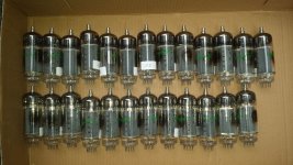
Taking inventory of all the stuff (wife calls it junk!) I have, I've come across 20 new Sylvania 20LF6 tubes. Putting ~500v or so on the plate and ~150v on the screen, any thoughts on transformer impedance for the balance between power and distortion? I have 4K transformers on hand, but if 3.3K or 2.2K are better choices, I'll buy them.
Thanks
Ray
Attachments
It appears to be a 6LW6 in a compactron base.
I use them triode strapped @320V with a 1k3 load for ~100W in push pull.
For SE triode, I'd probably use 2k or so.
I use them triode strapped @320V with a 1k3 load for ~100W in push pull.
For SE triode, I'd probably use 2k or so.
> Putting ~500v or so on the plate
Why?? These are LOW-impedance tubes. They made gobs of power in a 160V TV set. As audio they could run into Pdiss with 200V-250V of B+. The only reason to go higher is availability of audio OTs. If you raise the plate voltage you should also lower the G2 voltage for easier drive (less driver distortion) and slightly lower plate-bottoming voltage. I could see 600Vp 120V G2 at 5k load and 100W output like a couple 6550.
Why?? These are LOW-impedance tubes. They made gobs of power in a 160V TV set. As audio they could run into Pdiss with 200V-250V of B+. The only reason to go higher is availability of audio OTs. If you raise the plate voltage you should also lower the G2 voltage for easier drive (less driver distortion) and slightly lower plate-bottoming voltage. I could see 600Vp 120V G2 at 5k load and 100W output like a couple 6550.
They are really designed for switching, not linear use, specifically switching an inductive load, and their transconductance is large. The on-resistance is about 40 ohms. Alas the characteristic seems most linear at currents too high for practical use. Its clearly very definitely optimized for one use case only. I suspect the fun is in teasing some sort of performance out of it despite itself!
Could its switching performance be harnessed for class D?
Could its switching performance be harnessed for class D?
Most power tubes, audio or TV, have a near square law gm response for grid 1 (for reasonable current), so are well suited to P-P use, where 2nd Harmonic will cancel out. Seeing more 2nd harmonic in the TV tube's curves is not a concern.
If you want to get really low distortion, use some additional local N Fdbk too. Either Shunt "Schade" plate to grid, or something like the Citation II with plate to driver grids (crossed). Any additional distortion products in TV Sweeps (versus audio types) are low harmonic order anyway and easy to clean up with some local N Fdbk.
You could even just take the Citation II circuit and put some frame grid 12HL7 driver tubes in, in place of the 12BY7s, for -VERY- low distortion. (pin compatible even). Some re-work of the driver biasing of course. Some tweaking of the N Fdbks probably too (stability). You might find this to be -TOO- clean!
The big sweep tubes have plenty of current capability, so one can use lower Z OTs and lower B+ if you are not trying to absolutely maximize power output. Easier to get good bandwidth in the OT that way (for global N Fdbk).
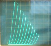
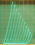
The quality of an -individual tube- for low distortion is most evident when configured for triode mode and curve traced. You will find that this selection method will give results far better (reduced 3rd and higher harmonics for pentode use!) than just picking an audio class versus a non audio class tube. Take a look at the selected 36MC6 sweep tube in triode mode below (1st pic). Or a selected 12HL7 in triode mode (2nd pic). Competitive with a 300B.
One can get even fancier and use emulation models to control the output tubes behavior with local N Fdbks. 1E7G would be a great triode model (in triode mode) to make TV sweeps emulate. Better than the 300B! (see pic3) One uses a differential driver for -each- output tube, with the model tube in the local N Fdbk path to its plate. A frame grid 12HL7 used for the other half of the diffl. driver stage will provide plenty of gm to enforce mirror performance between the model and the output tube.
If you want to get really low distortion, use some additional local N Fdbk too. Either Shunt "Schade" plate to grid, or something like the Citation II with plate to driver grids (crossed). Any additional distortion products in TV Sweeps (versus audio types) are low harmonic order anyway and easy to clean up with some local N Fdbk.
You could even just take the Citation II circuit and put some frame grid 12HL7 driver tubes in, in place of the 12BY7s, for -VERY- low distortion. (pin compatible even). Some re-work of the driver biasing of course. Some tweaking of the N Fdbks probably too (stability). You might find this to be -TOO- clean!
The big sweep tubes have plenty of current capability, so one can use lower Z OTs and lower B+ if you are not trying to absolutely maximize power output. Easier to get good bandwidth in the OT that way (for global N Fdbk).
The quality of an -individual tube- for low distortion is most evident when configured for triode mode and curve traced. You will find that this selection method will give results far better (reduced 3rd and higher harmonics for pentode use!) than just picking an audio class versus a non audio class tube. Take a look at the selected 36MC6 sweep tube in triode mode below (1st pic). Or a selected 12HL7 in triode mode (2nd pic). Competitive with a 300B.
One can get even fancier and use emulation models to control the output tubes behavior with local N Fdbks. 1E7G would be a great triode model (in triode mode) to make TV sweeps emulate. Better than the 300B! (see pic3) One uses a differential driver for -each- output tube, with the model tube in the local N Fdbk path to its plate. A frame grid 12HL7 used for the other half of the diffl. driver stage will provide plenty of gm to enforce mirror performance between the model and the output tube.
Attachments

Last edited:
It appears to be a 6LW6 in a compactron base.
I have no experience with a 'LF6 since I don't have any. The total heater power for the 20LF6 is 12 watts (20 volts @ 600 mA). The 26LW6 sucks 15.6 watts of heater power (26 volts @ 600 mA), so there are some differences.
I suspect the fun is in teasing some sort of performance out of it despite itself!
The fun is in getting GOBS OF POWER from a pair of tubes in a simple circuit without much effort.
Putting ~500v or so on the plate .....These are LOW-impedance tubes. They made gobs of power in a 160V TV set.
The tube will drop a fixed amount of voltage from cathode to plate for a given current at Vg=0. That voltage goes up as the current is increased. Yes, the peak current rating for the 'LW6 and "LF6 is 1.4 amps.
So if I squeeze 1 amp through the 20LF6 with the screen at 160 volts I will see about 40 volts from plate to cathode. Assuming 250 volts or so of B+, I'm losing about 20% of that in the tube.
Lets say I crank up the B+ to 500 volts and suck 1/2 an amp through the tube. Now I see 20 volts or so from plate to cathode. Now I'm only burning 4% of my plate voltage across the tube. In order to make life easier on the screen grid, you want to run it at the lowest voltage capable of generating the needed power output with good efficiency. For most big sweep tubes that's about 150 volts. For small sweeps, 120 to 150 volts. I have never needed over 175 volts.
On the flip side of the coin, you need a certain amount of idle current through any output tube to quiet down the crossover distortion and other artifacts of near class B operation. This depends on the tube, the load and how much feedback you are going to pile on.
As you crank the B+ higher and higher in search of more power, you run into plate dissipation limitations. The idle dissipation can be significant at high voltages. As this approaches 50 to 75% of the Pdiss rating of the tubes, it makes the point of maximum dissipation in the amp lower and lower, reducing the "duty cycle" of the amp (how often it can hit max power).
A pure class A amp burns maximum power in the tubes at idle. Plate dissipation drops as the amp is driven and is lowest as the amp hits clipping.
A pure class B amp dissipates no plate power at idle, and reaches peak dissipation near maximum undistorted power output.
The point of maximum plate dissipation is somewhere between these extremes in a class AB amp. Depending on the load impedance and the bias current it is usually somewhere 1/3 and 2/3 of maximum undistorted power.
I have tinkered with high powered TV sweep tube amps for about 20 years. The point of maximum plate efficiency tends toward pretty high B+ voltages.
I built some of Pete's Engineer's Amps with 6HJ5's (a 24 watt tube similar to a 6DQ5) and found that the best compromise for maximum power output was a 3300 ohm load on 600 to 625 volts with an idle current in the 25 to 30 mA range. This would produce 120 to 130 watts at the edge of clipping.
Maximum plate dissipation was in the 70 watt power output range, and reached about 30 watts per tube. Plate dissipation was around 24 watts per tube at 120 watts output. Clearly you wouldn't want to run a constant sine wave at 70 watts forever, but cranking it up to full tilt with music for hours was no problem. It was used for a rock band's PA system outdoors several times....and it still has the original tubes in it. Pete chose a more conservative setup for his mono block version with the same tubes. He gets 50 WPC.
A pair of 36LW6's will make over 225 watts on 650 volts into a 2500 ohm load. This kind of stuff is not for a first time build. The peak plate voltage can be in the 2 to 3 KV range with a real speaker load on music peaks. Even higher when you plug in a guitar a drive it 10 db past clipping with the speaker near resonance (common in a guitar amp).
Good Sunday everyone,
Thank you for your inputs on the 20LF6s. I do think I will spend the money and get different output transformers. I’ll do a coin toss whether I get 2.5K or 3.3K transformers unless there is a definite reason to get one over the other. Plate voltage will be 500v +/- 3% and screen will be 150v +/- 10%, both are regulated adjustable supplies.
Thanks
Ray
If you got one of those Hoefer PS500XT supplies with a fan in back, you'll be interested in one of these stone quiet 60mm fans:
SilenX(R) IXTREMA™ Pro IXP-34-16 60mm x 25mm Super Quiet 3 pin fan 16dBA 18 cfm | eBay
The new fan leads are too short, so I stripped and tinned a 1/4 inch of the red and black wires from the existing 12V fan plug in the Hoefer unit, then just push the tinned ends into the corresponding red and black socket positions on the new fan cord connector.
I also put a thin sheet of very porous flimsy foam in the box to absorb any sound resonating in the enclosure. Don't block the air flow though. Putting the cover on the unit had made it get audible again, so I figured some frequencies were resonating in the box.
Last edited:
I'm using an IHB155-0.12 Linear Supply for the screen(s). It's adjustable from 135–170v and for the plate, I'm using the "21st Century Maida Regulator" from Tom Christiansen/Neurochrome.
The transformer is big enough to do 1/2 amp.
The transformer is big enough to do 1/2 amp.
Good Monday everyone,
Would it be better to go with a lower plate voltage, let's say around ~450v and go with a 2500 Ω or 3300 Ω transformer? Looking at the data sheet, it appears the 6LF6/20LF6 can do some high current.
Thanks
Ray
Would it be better to go with a lower plate voltage, let's say around ~450v and go with a 2500 Ω or 3300 Ω transformer? Looking at the data sheet, it appears the 6LF6/20LF6 can do some high current.
Thanks
Ray
As I said, I use similar tubes triode connected. 120mA idle, 320V plate. Screen ties to place through 220R. 1k3 transformer. Push Pull. I haven't built an SE amp. If going pentode, I'd try about 250V... Are you planing PP or SE?
Last edited:
I get over 80W out of mine as triodes. As pentodes if you use a low enough Z (Like a Hammond 1650T or two toroidal transformers interleved) you should get lots.
Triodes are more linear, but the drive requirements are higher (like 200Vp-p).
My calculations show that you can even get about 80W out of a trioded pair at 250V if you use a 600R output transformer.
Triodes are more linear, but the drive requirements are higher (like 200Vp-p).
My calculations show that you can even get about 80W out of a trioded pair at 250V if you use a 600R output transformer.
Want my opinion? Take the stuff you have, the 500 volt supply, the 150 volt supply, the 20LF6's, and your 4K OPT, and put together a breadboard prototype of at least one channel. If your 4K OPT has multiple speaker taps, then you can run an 8 ohm load / speaker from the 16 ohm tap to put a 2 K load on the tubes. Even with 4 K you will be near 100 Watts, and the tubes will last forever.
You can also figure out what works good before you commit to a final design.
You can also figure out what works good before you commit to a final design.
- Home
- Amplifiers
- Tubes / Valves
- 20LF6s