Bricolo said:does this mean that most of the cd players, that use 16 bits dacs with oversampling, are loosing resolution?
In principle, yes. Unless the raw 16bit+ information in the oversampling filter is somehow packed in a 16 bit output format by noise shaping. I don't know if the old Philips 16 bit oversampling filter used noise shaping. It probably did.
Bernhard said:From the above thread:
So, there is error and in case of 8 x os the error will be 1/8 LSB if a nearest neighbour sample is taken instead of the right one ?
Nearest neighbour is of no relevance here. The above example pertains to the synchronisation/data selection process during ASRC.
rfbrw said:That thread was about Asynchronous sample rate conversion. What takes place in an oversampling filter like the DF1704 is different.
Not at all. At an abstracted mathematical level and the signal theory level they are one and the same: resampling to a new sample rate and low-pass filtering at the original sample rate.
Bernhard said:
Is there some detail lost using 16bit in 20bit out digital filter + 20bit converter 😕
A little bit. After the oversampling filter the entire amount of (filtered) information may require 32-48 bits for errorless representation. If it is properly converted to 20 bit (i.e. at least dithered and preferably noise shaped), the error made is of zero significance.
Bricolo said:I think there must be a relation between the n times oversampling your filter applies, and the x more bits it has at its output compared to its input
Not at all.
Such a relatation does exist (for a given set of system parameters) when discussing delta-sigma modulators. But we are merely discussing oversampling here.
Werner said:
A little bit. After the oversampling filter the entire amount of (filtered) information may require 32-48 bits for errorless representation. If it is properly converted to 20 bit (i.e. at least dithered and preferably noise shaped), the error made is of zero significance.
That leads me to the question if a very good 16bit chip has better resolution as a 18 or 20 bit chip.
If you take a perfect 20 bit DAC and chop off the four lower bits, you
end up with a 16 bit DAC with the equivalent linearity of a 20 bit device: i.e. it has 2^16 states, but the largest error is 1/2^20 of
full range.
With this extrapolated specification selected samples of the TDA1541 were known to perform significantly beyond 16 bit equivalent.
end up with a 16 bit DAC with the equivalent linearity of a 20 bit device: i.e. it has 2^16 states, but the largest error is 1/2^20 of
full range.
With this extrapolated specification selected samples of the TDA1541 were known to perform significantly beyond 16 bit equivalent.
Here's a little oversampling primer for the kind of oversampling going on in the DF1704 and similar devices.
1 - Insert a zero between each original sample in your input signal.
2 - Design the digital impulse response of your first oversampler. Essentially, find a windowed sinc function. (Sinc means sin(t)/t, windowing is fading in and fading out the sinc function so that it gets a finite time duration without causing ripples in the frequancy band = Gibb's phenomenon.) Sample the sinc function in the time domain so that its zeros are two samples apart. It now looks something like {-a 0 b 0 -c 0 d 1 d 0 -c 0 b 0 -a} where a, b, c, and d are positive constants with d>c>b>a.
To see if you like your windowed sinc, plot an fft of it in Matlab or Octave etc.
If you want to use 16-bit resolution (+-2^15-1) for your oversampler inpulse response, multiply the windowed sinc by 2^15-1 and round off the result. (Rounding off can be simple bit truncation but may also include dithering and noise shaping.) At this point, do a new fft to see if the digitized impulse response is up to the task. If it is not, try multiplying by k*(2^15-1) where you let k vary in small steps from, say, 0.95 to 1. Do a new fft for each value of k and pick the multiplication that gives you the best response in the frequency domain.
3 - Convolve your original input signal (with inserted zeros) with the oversampler's impulse response found in step 2.
4 - Round off the result of the convolution to fit the resolution you chose for the output of the oversampler. If this is the final oversampler, you typically choose the resolution of your DAC.
4 - You now have a twice oversampled signal. Each original sample is kept, and one new sample is inserted between each old one. Because of the zero insertion, the original samples were affected only by the {0 0 0 1 0 0 0}-part of the oversampler's impulse response, and thus passed right through it. The newly inserted samples were generated from the {-a b -c d d -c b -a}-part of the oversampler's impulse response. Because you may choose arbitrary resolution for your digital impulse response, there should be no connection between oversampling rate and required resolution.
5 - If you want 4x oversampling, insert new zeros and go again. For 8x oversampling, use this method three times. It is possible to utilize a wide variety of symmetries etc. to simplify hardware implementation.
6 - If you want to go straight to, say, 8x oversampling insert 7 zeros between each original sample and choose your windowed sinc so that it has zeros at every 8th sample.
Or, to answer your questions: NO, you don't loose data. Your original samples are kept. New samples are simply filled in between them.
Greetings,
Børge
If the filter is correctly implemented, then the original samples, at 16bit resolution at 44.1kHz should be replicated exactly unchanged at the output (for a synchronious filter). All the filter should be doing is inserting new samples between the original ones. For an 8x filter, it will insert 7 new samples between the original incoming samples while leaving the original samples untouched, except for scaling the 16bit value into a 20bit one.
At university I recall being shown the 'theoritical' calculation for this, which, although impratical in practise, did indeed leave the original samples intact. I'm not sure how the filtering is implemented in practice. Prehaps others may shed light on this (again, not asynchronious filting, there has been a great thread on this elsewhere).
Adrian
Hoist by his own petard?
Don't be a nudnik all your life, Werner, have a day off. At the requisite degree of abstraction a chicken egg is the same as a human foetus. This is not about theory and abstraction. It is actual devices and their methods of implemention. A distinction you seem to note when you wish to be contrary.
ray.
Originally posted by Werner
Not at all. At an abstracted mathematical level and the signal theory level they are one and the same: resampling to a new sample rate and low-pass filtering at the original sample rate.
Don't be a nudnik all your life, Werner, have a day off. At the requisite degree of abstraction a chicken egg is the same as a human foetus. This is not about theory and abstraction. It is actual devices and their methods of implemention. A distinction you seem to note when you wish to be contrary.
ray.
to Borges,
what you just described, isn't this the same what is done in the Decimation-dac as described at TNT-Audio?
TNT Decimaton
So, this actualy means that what is done by decimation is 2x oversampling except that there are no 'new' samples filled in between the original ones? (they will stay zero)
Chris
what you just described, isn't this the same what is done in the Decimation-dac as described at TNT-Audio?
TNT Decimaton
So, this actualy means that what is done by decimation is 2x oversampling except that there are no 'new' samples filled in between the original ones? (they will stay zero)
Chris
Werner said:If you take a perfect 20 bit DAC and chop off the four lower bits, you
end up with a 16 bit DAC with the equivalent linearity of a 20 bit device
Is there a schematic around to feed a 20bid DAC with 16 bit data ?
whats the problem? you only need to feed some zeros into. what else does the 8412 do with 16 bit data in a mode for dac with more than 16 bit?
till said:whats the problem? you only need to feed some zeros into. what else does the 8412 do with 16 bit data in a mode for dac with more than 16 bit?
So, Till, when can we expect the schematic?
Still the question:
Is there some detail lost using 16bit in 20bit out digital filter + 20bit converter
I'd say that if you don't oversample and basically don't use the 4 lsb, you can have no loss. If you also oversample, you can probably get 1/16 lsb error or better and greatly simplify post filtering. Probably many 20 bit implementations are not that good.
rfbrw said:
So, Till, when can we expect the schematic?
Yes, one for PCM61 18bit and one for PCM63 20bit.
Please.
There are recivers with 16,18,20 Bit output modes. You don´t expect ME to give schematics for them, you use them alle the days. In case a reciver is not what you want i can give a schematic: connect every input pin of the DAC to an output pin of you choice of a fast enough dsp. Else software. Unfortunaltely no company did the wise step to donate me a development pack for dsp´s so far....
No PCM61 or 63 DACs, as they do cost money and i will not spend when i get such fine DACs like AD1865 the preferred way..
No PCM61 or 63 DACs, as they do cost money and i will not spend when i get such fine DACs like AD1865 the preferred way..
I do not see any reason why a 20 Bit DAC must be more precise on its first 16 Bit than a 16 Bit DAC.
But the most loss in resolution would probably be from noise influence on the DAC, no matter if 16 or 20Bit.
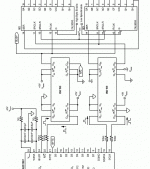
With lots of different capacitors and filters on the power supply i got no real difference in the measurable noise on the power supply rails. I suspect the noise comes from the digital side of the circuit, as jewilson told. What about this for the DACs:
But the most loss in resolution would probably be from noise influence on the DAC, no matter if 16 or 20Bit.
With lots of different capacitors and filters on the power supply i got no real difference in the measurable noise on the power supply rails. I suspect the noise comes from the digital side of the circuit, as jewilson told. What about this for the DACs:
Attachments
till said:I do not see any reason why a 20 Bit DAC must be more precise on its first 16 Bit than a 16 Bit DAC.
Because a true 20 bit DAC (as opposed to a marketing DAC), in order to be rightfully labeled so, can have a maximal error of 1 LSB, or in this case one 2^20th of full scale.
For a true 16 bit DAC the maximum error permitted is one 2^16th.
Yes in case any of those DACs reaches its specs in real world.
If you produce a 20 BIT DAC in a production process good enough to make it 20 Bit true resolution, you will be able to make an absolute precision 16 Bit DAC with the same process.
I do not see we fight with the generic resolution of the DAC in first line, we fight with the bad influences to its resolution. Else we would use those suggested by another member 1k$ true 18Bit DACs.
till said:There are recivers with 16,18,20 Bit output modes. You don´t expect ME to give schematics for them, you use them alle the days. In case a reciver is not what you want i can give a schematic: connect every input pin of the DAC to an output pin of you choice of a fast enough dsp. Else software. Unfortunaltely no company did the wise step to donate me a development pack for dsp´s so far....
No PCM61 or 63 DACs, as they do cost money and i will not spend when i get such fine DACs like AD1865 the preferred way..
Take a chill pill and relax Till 😎😎, I wasn't serious as I am well aware of your dsp fetish and pin phobia.
These two links (site is in Russian) should get you going.Bernhard said:
Yes, one for PCM61 18bit and one for PCM63 20bit.
Please.
http://www.zeuslab.newmail.ru/shiftreg.htm
http://www.zeuslab.newmail.ru/images/i2s_2.jpg
I'd suggest connecting the YM3623 or CS8412 to the PCM63 in stopped clock mode but I fear it might upset the clock fetishists😀 😀
Take a chill pill and relax Till , I wasn't serious as I am well aware of your dsp fetish and pin phobia.
thanks, that will help.
I have not really DSP phobia, i think DSP is the way to go, as it would make it possible to have a) balanced DACs, b) separate DACs for each speaker system, thus no crossover in the analog domain needed.
What i dont like are SMD packages, but the first DSP - like microcontroller is avaiable in DIP at microchip. And i never made software for a DSP...
till said:If you produce a 20 BIT DAC in a production process good enough to make it 20 Bit true resolution, you will be able to make an absolute precision 16 Bit DAC with the same process.
My idea:
16bit DAC have 1 LSB linearity error.
20bit dac have 1 LSB linearity error. I hope so

Every stage of the 20bit DAC need to be as accurate so that this 1 LSB can be achieved.
So if it is fed with 16 + 4 empty bit data, linearity error will be strongly reduced.
No oversampling, no interpolation, no risk of loss, compared to real 20bit.
- Status
- Not open for further replies.
- Home
- Source & Line
- Digital Source
- 20bit DAC - where does the resolution come from ?