andrew t.....
my respect andrew t !!!! you have been always a catalyst to our talks and to many of my posts
what you say is very correct ....my mistake i was in a kind of rush today ....been very busy ....
please notice :
in the original schematic of dr bora there was no resistors placed in this drawing these resistors where added and you are very correct half of them are conected to the wrong pin
since this amp is a quasi the resistors of the -rail sould be placed in the other side. IE: between the power rail and the mosfet and NOT !!! in the out of the mosfet ....
as about the amp it shelf i also dont recoment it and especially for high rail voltage and or pa use ore abuse .....
in low rail voltage like 40+40 volts its a very sweet thing with a very warm sound considering the simplicity is made of
thank you andrew t
Thanks for all the help Sakis 🙂
Do you pehaps have a schematic with the modifications?
Thanks Again
Do you pehaps have a schematic with the modifications?
Thanks Again
legend 4.....
in high rail voltage like above 60 volts never worked in my hands
mostof modifications made had side effects also either improoving power but loose stability or improove gain but create offset or improove stability and loose quality
i had the thing in my hands over a year trying to play with various suggestion of many forum and other people but results where not good
i can give you many mods that we tryied in the past and also tell you many about the side effects but after that you are on your own
simlply if you change how differntial input stage is working and creat a constant current source vext to it ( needed ) and then to almost the same for vas amplifier stage and then use complementary mosfet not quasi topology with removing of phase inverter circuit ....... you may have an amplifier working but is not going to be a legend 4 any more ...then you are in a esp 101 project or an antony holton amp and goes on
for example i have constructed p101 from rod elliot ( also really nice guy ) and it prooved to be what really promissed ....good sound really powerfull but having so many problems trying to mod legend 4 i decided not to run mosfets any more and go back to bjt in avery simple but extremelly powerfull schematic that i run now for almost a year in quiet heavy PA application that works just perfectly ........
keeping the post so long let me tell you a story
once come to my lab a very old amp very rowbust construction at the time created with quasi technology and bjt greek made also but a lot of out devices and a lot of overdesign on almost everything like cooled drivers located on heatsinks vas stages also on heatsinks source resistors rated 10w each and goes on
supply with almost 100 volts pair rail on bench could produce almost 600w @ 8R (presuming that had filtercaps and trafo to fit the task) also had power devices for it
but when you montage the all thing it prooved that almost only 450w of it where really usefull ...... and this wasnt because trafos where too small or caps ..... it was because in the base of the out bjt's where protection circuit to secure that the out devices where working on a safe operation area of course also depenting on temperature and input signal
ie : even if you have a legend that produces almost 200w ....HOW MUCH OF IT IS USEFULL???? AND FOR HOW LONG ????
the rest is up to you
mods will follow up later
bets regards sakis
I said don't copy this schematic/design and now Sakis is saying much the same.djmarvellous said:Thanks for all the help Sakis 🙂
Do you perhaps have a schematic with the modifications?
Choose another better design.
WELL ....
A) one mod we did and seem to work ok is to replace two resistors of 4K7 feed from +railto bootsrap cap and then to vas from 4K7 to 6K8....
the concept of this mod was to maintain the same current flow to vas amplifier than it was with 40+40 volts rail it seemed to work ok
by concept this can be also applied to uper ltp stage but then you have to do something in the lower ltp and this is nothing i can calculate
if i remember well thi mod alters the sensitivity of the amp to more than 2 volts to get full power
then after that you can replace the feedback resistor from 470R to 270R and things are getting kind of better
but then again offset of about -100mv is formated in the out
dead end again .....
B) also ... the mod with these resistors seem to work ok with rails of about 56 volts and power of almost 200w and stable but offset is still there also stable ....
100mv offset for amplifier is too much and tents to multiply on full power
other test that had to do with the input and ltp prooved nothing zenner added prooved nothing
i have some notes of some other tests that i have to dig out and will be also available to you
cause of all this i lost my contact with dr bora we missunderstand eachother and bad things where said between us i really mean nothing bad about this guy
when he gave me his schematic FOR FREE !!! from his e mail i thought that this was a plug and play device ready to operate in voltage of at least 60 volts ( actually this was also drawn in the original schematic ) but this never worked.... STILL i will remind you again that in rails 40+40 volts is a very nice amp to my ears
....... anyway you are welcome to try with him also his e mail is available at the forum and also if you manage to go further than i did then may be we can help each other after all
regards sakis
one thing i missed
it seemed that when we replaced this network of resistors that feed the vas idle current was more stable and also the trimmer posistion was much diferent ......
what i am trying to say is that when you lift your rails to 60+60 volts idle current is consumed arround the vas area and not the out transistors ....... so after you replace the resistors then real idle can be achived ......
exaplain : before the resistor change and with a ma meter inserted in serious you ajust the trimmer to read idle of 100ma then you go to the source resistors to see about voltage drop and you see zilts nothing at all so mosfets are not biased
after the mod there was voltage drop in the source resistors also meaning that idle current was consumed properly to provide bias to the mosfets
since my theory is cr***p all this is academic is simply the results of otherpeople opinion and some tests
thats it
Thanks Sakis
for all the info & Help greatly Apreciated
Would you mind Sharing with Me
the Schemetic & Pcb for the
bjt Amp in avery simple but extremelly powerfull schematic that U run now for almost a year in quiet heavy PA application that works just perfectly?
Would Apreciate that as My aplication is Mostly PA.
Thanks In Advance.
well.....
this one ....like p101 from rod elliot is protected ......rod is been working a lot for his projects and most of them he give for free lets be nice to him
before posting this i have to confirm with the designer .....you see this in no kids stuff is machine that if you operate and construct nicelly will produce almost 1KW @ 4R
to my understanding though this schematic is based on 2sa1943 and 2sc 5200 typical for our times ( a lot of them ) it operates in ab class and it can be runned in almost +- 110 volt but except the normal quality than a thing like that can produce its a very well guarded thing ....... drives and output currents temprature and thermal runaway is very well taken care of ...so this why i like it so much
so i will check and let you know ......
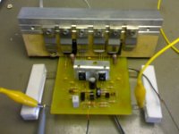
Quasi's Nmos200
Just built the Quasi's Nmos200 with nothing but ceramic caps
and I was quite Impressed
The Sound is Amaizing
The Amp is Dead Quiet
Bass is Very Good
ran It on +-40V Rails
IRFP250 outputs
This is My 1st Nchanel Mos Amp
& I have to say I Really Expected less from this Amp but I Was Proven Wrong
Im Busy Building a Quasi's Nmos500
& Dr Borivoje Jagodic Legend Stage Master
Will Keep U Posted on The Progress
Thanks for the Schemetics & Pcb Layouts!!!
U Guys Rock 😎
"and could you tell me if just adding more outputs & beefing up my
power supply would upgrade my amp to a 800w?
Hi Djmarvellous
Hybrid amps are build by a South African firm. I'm trying to obtain more info about them myself. This is what I've gotten hold of so far: The smaller board is a standard "driver" board for the Hybrid range of amps. It can be used up to 500W per channel. I have one of the A1000 amps if you would like some more info on it. It uses 10 output devices and a PSU voltage rail of 80-90V per rail.
Re: Quasi's Nmos200
😉 cool
djmarvellous said:Just built the Quasi's Nmos200 with nothing but ceramic caps
and I was quite Impressed
The Sound is Amaizing
The Amp is Dead Quiet
Bass is Very Good
ran It on +-40V Rails
IRFP250 outputs
This is My 1st Nchanel Mos Amp
& I have to say I Really Expected less from this Amp but I Was Proven Wrong
Im Busy Building a Quasi's Nmos500
& Dr Borivoje Jagodic Legend Stage Master
Will Keep U Posted on The Progress
Thanks for the Schemetics & Pcb Layouts!!!
U Guys Rock 😎
😉 cool
Thanks minniew
A couple of Questions....
1. Does the A1000 use the same small driver board as used in the A400?
2. What the co Name that makes these Amps?
3. it really strange that they would drive so many otputs with to92 transistors
most amps use bigger transistors to drive the outputs.
Has yours ever failed?
Thanks.
just a Question quasi
Hi quasi
Just a question...
Would it be wise to use the NMos200 board as a driver to drive lets say 3pairs outputs?
(oviously substituting the resistor values of the n500 schematic)
Thanks In Advance.
Hi quasi
Just a question...
Would it be wise to use the NMos200 board as a driver to drive lets say 3pairs outputs?
(oviously substituting the resistor values of the n500 schematic)
Thanks In Advance.
"Has yours ever failed"
No not as yet, but I have not driven it ti max as my speakers can't handle it. One thing I can tell you is on all the A series amps there is a "stock fault". In the driver board a resistor overheats and burns out taking the amp's outputs with it. I have several of those burnt boards. (Not mine, got them from a repair shop) I repaired them and re used them on a repaired Hybrid A400 and it has been driven quite hard and I have not yet lost my A400. These amps must just be kept as cool as possible. With regard to the company I am yet to find their name. I'll let you know as soon as I do.
No not as yet, but I have not driven it ti max as my speakers can't handle it. One thing I can tell you is on all the A series amps there is a "stock fault". In the driver board a resistor overheats and burns out taking the amp's outputs with it. I have several of those burnt boards. (Not mine, got them from a repair shop) I repaired them and re used them on a repaired Hybrid A400 and it has been driven quite hard and I have not yet lost my A400. These amps must just be kept as cool as possible. With regard to the company I am yet to find their name. I'll let you know as soon as I do.
Hi. Sorry my previous post seemed to be in error. I thought that these amps were made is SA but it would seem that they are imported. I have gotten hold of the company's telephone number but it is listed as not in use any more.
Re: just a Question quasi
The Nmos200 board could be modified to take additional output pairs quite easily and as you suggest a few component values changed to accept higher rails. The only difficulty I see is getting rid of the output stage heat via the mounting bracket. On the Nmos 350/500 the output transistors mount directly on the heatsink rather than on a bracket. This should be done with the Nmos200 layout if higher powers are contemplated.
Sorry...don't mean to hijack this thread.
Cheers
Q
djmarvellous said:Hi quasi
Just a question...
Would it be wise to use the NMos200 board as a driver to drive lets say 3pairs outputs?
(oviously substituting the resistor values of the n500 schematic)
Thanks In Advance.
The Nmos200 board could be modified to take additional output pairs quite easily and as you suggest a few component values changed to accept higher rails. The only difficulty I see is getting rid of the output stage heat via the mounting bracket. On the Nmos 350/500 the output transistors mount directly on the heatsink rather than on a bracket. This should be done with the Nmos200 layout if higher powers are contemplated.
Sorry...don't mean to hijack this thread.
Cheers
Q
quasi
Another Question...
I just noticed that My N200 is missing R6 the 33R resistor
I must have forgotten to put it in...yet it is still working
what then is the purpose for it?
is it stability maybe?
Thanks in Advance
Another Question...
I just noticed that My N200 is missing R6 the 33R resistor
I must have forgotten to put it in...yet it is still working
what then is the purpose for it?
is it stability maybe?
Thanks in Advance
- Status
- Not open for further replies.
- Home
- Amplifiers
- Solid State
- 200w to 800w or am i missing something?