I have a amplifier "Hybrid 200Ab"
wich is a 100w X2 power amp
& my friend has the 400W X2 power amp (Ab800)
wich blew 1 chanell this past weekend
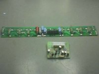
upon openning it and having a look inside
I found that his amplifier was just like mine inside
except that his has 4X 2SK1058 & 2SJ162 Pairs per chanel
while mine only has 2pairs
1 of his driver boards had burned out
i took 1 of mine & put it in his amp and the amp was operational again
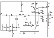
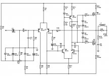
I then reverse engineered the schemetic as I could not find it anywhere.
I have attached it here...
could you guys please check it for erros
and could you tell me if just adding more outputs & beefing up my
power supply would upgrade my amp to a 800w?
Thanks in Advance🙂
wich is a 100w X2 power amp
& my friend has the 400W X2 power amp (Ab800)
wich blew 1 chanell this past weekend
upon openning it and having a look inside
I found that his amplifier was just like mine inside
except that his has 4X 2SK1058 & 2SJ162 Pairs per chanel
while mine only has 2pairs
1 of his driver boards had burned out
i took 1 of mine & put it in his amp and the amp was operational again
I then reverse engineered the schemetic as I could not find it anywhere.
I have attached it here...
could you guys please check it for erros
and could you tell me if just adding more outputs & beefing up my
power supply would upgrade my amp to a 800w?
Thanks in Advance🙂
Attachments

For 100W thats a fairly OK design - pretty much a copy of the Hitachi app note for their audio mosfets. Not very advanced, but passable.
For any further power, it's dreadful... the MPSA42/92 used in the second stage will be dissipating a lot of heat, and burn out quite easily. That is probably what killed his amp. Also, theres no driver stage for the mosfets, which is unacceptable when driving many pairs.
Consider building him something better, like one of Quasi's amp's, or one of Anthony Holton's. You've the most expensive parts already - case, heatsink, power supply. It depends what he wants it for - 400W is more for PA use than domestic use, I would think. 100W into 8 ohms is plenty in a domestic amplifier.
That schematic looks flawed. How is the upper mosfet supposed to achieve bias?
The collector of Q5 should lead to the gate resistor of Q6... Missing wire.
The collector of Q5 should lead to the gate resistor of Q6... Missing wire.
I suspect you missed the trace off from the bias generator to the upper mosfet.
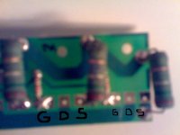
I think maybe you got the sources and drains mixed up on the output mosfets - they are GSD - the resistors should be in the sources.
I think maybe you got the sources and drains mixed up on the output mosfets - they are GSD - the resistors should be in the sources.
just double checked the Resistors are on the Drains
is there any improvements I could do to this amp to make it more relieble?
Thanks in Advance...
is there any improvements I could do to this amp to make it more relieble?
Thanks in Advance...
The P-channel FET, Q7 is upside down. The source should be attached to the output instead of the V- rail. As well, the drain should be on the V- rail.
It would seemingly make more sense to have the output resistors R20 and R21 attached to the sources of the FETs, which then would lead to the output.
It would seemingly make more sense to have the output resistors R20 and R21 attached to the sources of the FETs, which then would lead to the output.
Hi,
basic question is: can more power be got by adding output devices?
Basic answer, yes.
As you double the output devices you double the current capacity of the output stage. This allows the output stage to feed a half impedance load to the same drive voltage.
So your 1pair for 100W into 8r0 becomes 2pair for 200W into 4r0.
4pair could do near 400W into 2r0 from the same PSU voltage, if the PSU could hold up under the massive current now demanded.
A new much bigger transformer and enormous smoothing capacitance could get you to 800W into 2r0, but you would retain none of the existing amplifier. It becomes a throw it away and start again project.
A word of caution for real speaker loads. The temperature de-rated SOAR for a reactive load is very closely approached by a severe speaker load. Reduce those resistive maximum powers by about half, if your speakers demand great current rather than behave as benign resistors.
The existing voltage amplifier is seriously flawed in it's ability to drive HF into reactive loading.
You could replace the voltage amp very cheaply and keep the existing PSU & case & heatsinks & output stage.
The 1058&162 need quiescent bias current of at least 50mA per pair and preferably 100mA per pair.
Going to 4pair would dissipate twice as much heat and require a much bigger heatsink as well as a big upgrade in the PSU to support the high quiescent current that these FETs deserve to give of their best.
Duo said:The P-channel FET, Q7 is upside down. The source should be attached to the output instead of the V- rail. As well, the drain should be on the V- rail.
It would seemingly make more sense to have the output resistors R20 and R21 attached to the sources of the FETs, which then would lead to the output.
The laterals won't need any source resistors due to their low transconductance and tempco crossover at only 100mA 🙂 Are they really in the drains? (the center lead is source on these transistors) Their purpose then would be to provide an easy way of measuring bias current.
I do agree that MPSA42/92 if that really are the parts used are severly underrated for the VAS.
 What's the rail voltage? They will be dissipating 500mW or something at idle, which is quite close to the maximum allowed at 25 degrees! I'd use MJE340/350 or similarly rated transistors and also increase the VAS current OR decrease the VAS current and add a driver stage with those transistors.
BTW, I have posted the answer to my Lateral MOSFET torture now, and this kind of explains why zeners usually are enough to protect this type of transistor. It would be interesting to know though what causes the "thyristor" effect observed that shuts down the transistors. Any ideas?
http://www.diyaudio.com/forums/showthread.php?postid=1342573#post1342573
multi-parallel Laterals need balancing source resistors.megajocke said:
The laterals won't need any source resistors due to their low transconductance and tempco crossover at only 100mA 🙂 ............ this kind of explains why zeners usually are enough to protect this type of transistor.
Even matching to a few mV results in significant differences in drain currents at quiescent and worse when delivering output current.
I see he has c11V +diode zener protection which is better than the usual 15V often fitted. But 6 to 8V zeners would be more effective.
http://www.jaycar.com.au/images_uploaded/2SK10568.PDF
They really are source resistors, the pinout is G-S-D, not G-D-S on these! 😀
I agree that current sharing on idle might be much better with the resistors, but at higher powers the current decreases a lot with temperature. I do not suggest removing them though, I just wanted to point out that often they are not needed. When they are used it is important that they are low-inductance types (the ones in the picture look okay) or there will be oscillation problems.
Hafler didn't use them for example in their amps:
http://www.hafler.com/techsupport/pdf/MAN1461C_P1500_P3000_man.pdf
http://www.hafler.com/techsupport/pdf/DH-500_amp_man.pdf
http://www.hafler.com/techsupport/pdf/DH-220_amp_man.pdf
http://www.hafler.com/techsupport/pdf/P7000_amp_man.pdf
Vertical fets on the other hand will need them, but they are very different...
Thanks duo I Q7 was indeed Upside down
I have now corected this 😉
I have attached the new corrected schemetic
megajocke 500mw wow that is indeed too much
could I just directly replace with MJE340/350 without any other modifications?
would they need heat sinks?
How would I Go about decreasing the VAS current and adding a driver stage?
Thanks in Advance
Hi, djmarvellous
What is voltage of PSU for tis amp, with 4X 2SK1058 & 2SJ162 Pairs per chanel.
Regards zeoN_Rider
What is voltage of PSU for tis amp, with 4X 2SK1058 & 2SJ162 Pairs per chanel.
Regards zeoN_Rider
+-65V for the one with 4 pairs per channel (ab800)
and +- 45 for my one with 1Pair per Channel (ab200)
and +- 45 for my one with 1Pair per Channel (ab200)
Would anuone please point me in the right direction
in modding this amp into a reliable amp?
Thanks in Advance
in modding this amp into a reliable amp?
Thanks in Advance
- Status
- Not open for further replies.
- Home
- Amplifiers
- Solid State
- 200w to 800w or am i missing something?