I'm self-doubting whether to do a better 2x4" MEH or (using 16ohm 4FE35) 4x4" square MEH. With my "more coherent" 1st-order-notched T/MM I think I heard a bit of HF108 ketone polymer membrane sound signature, trading steely edged strings for hard plastickyness -- a little bit. My Minmeh 2nd-order-notched, flatter FR didn't do that.
Please consider giving "reflector point-source" topology a test. Just point a small car tweeter at midwoofer dustcap and move it around until their acoustic centers (one real, one reflection) became coincident and the sound holographic. Also LX which reduced the acoustic centers gap beween midtweeter and up-firing midwoofer.To me, the single-point source within the coverage-volume is the most important feature of a MEH, and I don't know of any other topology able to do that.
Last edited:

Omnidirectional has it's use and users, but it can be hard to find a proper placement, taking up to much space (that could be used for a BIG horn 🙂. Depending on what ones intended use is, probably somewhere between critical listening and background noise, one should aim for a suitable system. I would prefer something that is true to the recording, so I would try to avoid early reflections (<10ms) to "hide" the room. My idea for a horn is to utilize the ability to (somewhat) control the beamwidht, and getting single-point source would be a big benefit. If in need of more reflections, one could toe the speakers in/out, but that would demand speakers suited for the listening room and/or vice versa. DIY can make this happen 🙂Please consider giving "reflector point-source" topology a test. Just point a small car tweeter at midwoofer dustcap and move it around until their acoustic centers (one real, one reflection) became coincident and the sound holographic. Also LX which reduced the acoustic centers gap beween midtweeter and up-firing midwoofer.
Sure, depends on the room, placement, and seating. Many ways to reduce dispersion & reflections; not so many to get point-source (as you've said). LX cardioid-dipole can be close to walls. Point-source reflector size/shape is diy to taste (midwoofer face front or up). I'm doing MEH in a smallish room only 3.5x6m so directivity helps. Not really sure 8cm vs 12cm effective CtoC would make much difference far-field in a large space.I would try to avoid early reflections (<10ms) to "hide" the room. My idea for a horn is to utilize the ability to (somewhat) control the beamwidht, and getting single-point source would be a big benefit.
Last edited:
^ Agree. CtC-distances can be somewhat relaxed with correct filtering, details at Linkwitzlab. My listening room is somewhat like Yours, +low ceiling LWH 717x336x219cm, so for me a 64x46 degree horn would be nice, but it has to be BIG to get that pattern and have loading down to the Schroeder-frequency. One not-so-obvious possibility with MEH is the low group delay at low (bass) frequencies. Any abrupt changes in a horn will give reflections, reflections will give a ragged impedance (and freq) response, the same seems to apply for the mouth => a rounded mouth should be beneficial.
Sketch of predicted in-room reflexes. Dots are ego-centric listening-positions 😎

Sketch of predicted in-room reflexes. Dots are ego-centric listening-positions 😎
Updates on the throat adaptor experiments.
I made an R-OSSE waveguide in ATH and printed it in PLA using a 0.6 mm nozzle and 0.18 mm layer height. It resulted in a super smooth finish, the Bambulab A1 is such a good printer for the price. I was going to use a two-part epoxy to glue it together, but one part of the epoxy had hardened (probably too old), so I went with both superglue and contact glue. It’s probably not very strong, but it should work for this experiment.
The waveguide has a 1.4 mm entry with a 9.5 degree entry angle. I also designed an adaptor going from 1 inch to 1.4 inch with a 9.5 degree angle, it’s about 61 mm long. The throat adaptor with the mid entry point is 120 mm long, so the horn throat is 181 mm from the CD entry and 116 mm from the mid entry ports. It looks quite ridiculous, and I didn’t expect it to work very well. I used the mid rear chambers from the V1 MEH.

Here are the raw measurements:

A bit disappointing seeing the low extension of the mids but what can you expect with these small slits. However, the compression driver is performing well in this configuration, and it’s surprisingly flat. I did some rough EQ and brought the higher range of the mids down so I could cross them over at 150 Hz. Not ideal but it seems to work okayish. It would probably work better to use the mids between 600-1300hz, but my goal was to use them all the way down to 150hz.
Here is the response after EQ and crossover. There is a notch at around 310hz

Directivity response (normalized). The CD is doing great, but the mids are rougher.

For the next version, I’d like to skip the 1-to-1.4 inch converter and make a new MEH throat adapter that goes from 1 inch to 1.4 inch. The adapter's exit angle would match the throats entry of 9.5 degrees.
I’m also trying to figure out what changes would improve the mid tap ports. They definitely need to be bigger, and moving them closer to the horn throat should help to increase the low end.
The slit is currently 44 mm to 84 mm away from the compression driver. That corresponds to half a wavelength of 3897 Hz to 2041 Hz. This somewhat aligns with the notches in the response. Interestingly, the response around 3 kHz, right between those two notches looks good. Could I make the slit more gradual, shaped like an eye or a teardrop, to reduce harsh reflections? The edges of the slit aren’t rounded either, smoothing them out might improve the response.
If I move the mid ports further from the compression driver’s entry, I could likely shift the notch lower. Ideally, they should align with the crossover point. I assume they’d need to be half a wavelength from the CD entry to create a cancellation notch. So, for a crossover at 1300 Hz, the distance would need to be about 13.19 cm. But that would break Danley’s ¼-wavelength rule between the mid and the CD.
In the first throat adapter test, the CD’s response was my main concern and the mids looked pretty decent, considering they were open-back. Now the mids are worse. Is the distance from the horn throat the culprit? Given all this, I think placing the mid entry ports as close to the throat as possible is probably best. Maybe even on the horn walls? But then I’m back to square one. No… I’ll keep exploring this idea of putting the mid ports on the throat adapter.
I’ve been listening to it while writing this. The high frequencies are beautiful, smoother than on my previous MEHs, less metallic, which is great. The mids, though, are a bit muffled, not so great.
Anyway, I’m off on holiday now, so the exploration will continue in about two weeks.
I made an R-OSSE waveguide in ATH and printed it in PLA using a 0.6 mm nozzle and 0.18 mm layer height. It resulted in a super smooth finish, the Bambulab A1 is such a good printer for the price. I was going to use a two-part epoxy to glue it together, but one part of the epoxy had hardened (probably too old), so I went with both superglue and contact glue. It’s probably not very strong, but it should work for this experiment.
The waveguide has a 1.4 mm entry with a 9.5 degree entry angle. I also designed an adaptor going from 1 inch to 1.4 inch with a 9.5 degree angle, it’s about 61 mm long. The throat adaptor with the mid entry point is 120 mm long, so the horn throat is 181 mm from the CD entry and 116 mm from the mid entry ports. It looks quite ridiculous, and I didn’t expect it to work very well. I used the mid rear chambers from the V1 MEH.
Here are the raw measurements:
A bit disappointing seeing the low extension of the mids but what can you expect with these small slits. However, the compression driver is performing well in this configuration, and it’s surprisingly flat. I did some rough EQ and brought the higher range of the mids down so I could cross them over at 150 Hz. Not ideal but it seems to work okayish. It would probably work better to use the mids between 600-1300hz, but my goal was to use them all the way down to 150hz.
Here is the response after EQ and crossover. There is a notch at around 310hz
Directivity response (normalized). The CD is doing great, but the mids are rougher.
For the next version, I’d like to skip the 1-to-1.4 inch converter and make a new MEH throat adapter that goes from 1 inch to 1.4 inch. The adapter's exit angle would match the throats entry of 9.5 degrees.
I’m also trying to figure out what changes would improve the mid tap ports. They definitely need to be bigger, and moving them closer to the horn throat should help to increase the low end.
The slit is currently 44 mm to 84 mm away from the compression driver. That corresponds to half a wavelength of 3897 Hz to 2041 Hz. This somewhat aligns with the notches in the response. Interestingly, the response around 3 kHz, right between those two notches looks good. Could I make the slit more gradual, shaped like an eye or a teardrop, to reduce harsh reflections? The edges of the slit aren’t rounded either, smoothing them out might improve the response.
If I move the mid ports further from the compression driver’s entry, I could likely shift the notch lower. Ideally, they should align with the crossover point. I assume they’d need to be half a wavelength from the CD entry to create a cancellation notch. So, for a crossover at 1300 Hz, the distance would need to be about 13.19 cm. But that would break Danley’s ¼-wavelength rule between the mid and the CD.
In the first throat adapter test, the CD’s response was my main concern and the mids looked pretty decent, considering they were open-back. Now the mids are worse. Is the distance from the horn throat the culprit? Given all this, I think placing the mid entry ports as close to the throat as possible is probably best. Maybe even on the horn walls? But then I’m back to square one. No… I’ll keep exploring this idea of putting the mid ports on the throat adapter.
I’ve been listening to it while writing this. The high frequencies are beautiful, smoother than on my previous MEHs, less metallic, which is great. The mids, though, are a bit muffled, not so great.
Anyway, I’m off on holiday now, so the exploration will continue in about two weeks.
Nice to see You are testing out ideas 🙂 I think You are into something good with the CD adapter.
The rule of horn cross-section area(CSA=((c/f)^2)/4pi) where the ports enters the horn is challenged, maybe this can be part of the reason to the lacking low response of the mid's?
Can also be the volume of the mid's rear chamber? Distance between ports is definitely not to high.
Not to forget Danleys advice about flare rate wrt frequency, which I don't fully understand how to determine.
Please do test the idea of eye-shaped ports.
As I understand, the notch will be where the center of the mid ports are 1/4wL (90deg) from the reflective surface, which some says is the membrane of the CD, or the grill of the CD, or the horn apex... I think all of these give some reflections(frequency dependent) so the reflected wave will be somewhat smeared out in time and amplitude, which will have an effect on the acoustic lowpass rolloff steepness.
A narrow throat might give some interesting results for high SPL, maybe more distortion and intermodulation between CD and mids.
For aligning the pressure wave from the CD and the mid, I think the distance from the mid's voicecoil through the port and to a point on the horn axis can be made such that You might avoid using any time delay between CD and mid.
Enjoy Your holiday !
Deeply impressive printing and construction there, thank you for posting the pictures; it is inspiring to see!
FWIW bigger rear chambers can help the low end in (what are effectively) such bandpass arrangements. Larger (or at least less tiny) front chambers can help widen the pass band and increase efficiency (so cone fillers may not 'necessarily' be advantageous unless you're struggling to reach up to the compression driver's range).
But ultimately these little drivers are quite displacement-limited for bass duties, except at low SPLs. Their small Sd means the excursion needed shoots up at low frequencies; here is a 4FE35 with a 5L rear chamber and a tap size about 1/8th of Sd:
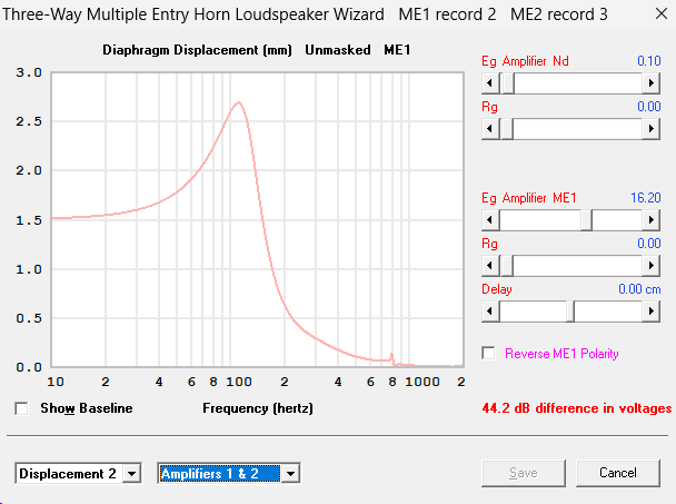
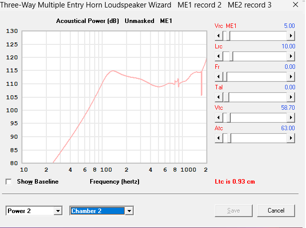
(EDIT: here the 4FE35 was simulated as a mid-range; it could likely be optimised better had it been intended as a 2-way)
So with EQ they would work at modest SPLs, perhaps mated to a subwoofer. But of course more or bigger drivers would offer more output; maybe four smaller or two 6" for my taste would seem a useful size. Though it is more tricky to reach up to a ~1khz crossover as they get bigger (one of the trade-offs with a 2-way MEH); the biggest I've seen achieved are 8" drivers in a 2-way - after that, a compression driver that can go lower seems necessary, except at very low spl. Meaty larger format compression drivers can be crossed lower to much bigger drivers, but can suffer at the top end; how much is somewhat related to the waveguide/horn type (for instance Geddes didn't like greater than 1" drivers on his oblate spheroid guides).
Often, moving the taps closer to the compression driver is about raising the top end of the cone drivers rather than the lower end. Due to the usual aim of keeping the taps within 1/4 wavelength of the compression driver's effective acoustic centre (which is generally somewhere inside the compression driver itself) and also within 1/4 wavelength of each other, although on narrower dispersion horns that 1/4 wavelength can be relaxed slightly. So the closer the taps are, the higher in frequency this ideal relationship will be maintained.
But secondly there is the null caused by reflections going down and bouncing back up the horn. This occurs when the total reflected distance (down and back) is half a wavelength, so in effect the one-way distance is again 1/4 wavelength. Though this time the distance is measured from where the reflection occurs, typically around the throat or the compression-driver screen in a unity horn though it varies - but might be quite different with your new throat profile. This null can be usefully placed to coincide with the crossover slope, or failing that to be pushed above (out of) the range at which the cone drivers are to operate. If your null is falling within the cone driver's intended range then yes, closer tap placement could certainly help.
Thirdly there is the expansion rate of the horn at the point where the taps enter. Arguably this is mostly about horn loading, which can also help the low end. Your throat adaptor seems to have the taps in a tubular non-expanding section of the throat? I haven't looked at the effects of that myself (and TBH am more into waveguides for their directivity, I don't know much about horn loading) so I don't really know what the effects might be, but feel it could be worth considering unless you've already done so.
FWIW bigger rear chambers can help the low end in (what are effectively) such bandpass arrangements. Larger (or at least less tiny) front chambers can help widen the pass band and increase efficiency (so cone fillers may not 'necessarily' be advantageous unless you're struggling to reach up to the compression driver's range).
But ultimately these little drivers are quite displacement-limited for bass duties, except at low SPLs. Their small Sd means the excursion needed shoots up at low frequencies; here is a 4FE35 with a 5L rear chamber and a tap size about 1/8th of Sd:
(EDIT: here the 4FE35 was simulated as a mid-range; it could likely be optimised better had it been intended as a 2-way)
So with EQ they would work at modest SPLs, perhaps mated to a subwoofer. But of course more or bigger drivers would offer more output; maybe four smaller or two 6" for my taste would seem a useful size. Though it is more tricky to reach up to a ~1khz crossover as they get bigger (one of the trade-offs with a 2-way MEH); the biggest I've seen achieved are 8" drivers in a 2-way - after that, a compression driver that can go lower seems necessary, except at very low spl. Meaty larger format compression drivers can be crossed lower to much bigger drivers, but can suffer at the top end; how much is somewhat related to the waveguide/horn type (for instance Geddes didn't like greater than 1" drivers on his oblate spheroid guides).
Often, moving the taps closer to the compression driver is about raising the top end of the cone drivers rather than the lower end. Due to the usual aim of keeping the taps within 1/4 wavelength of the compression driver's effective acoustic centre (which is generally somewhere inside the compression driver itself) and also within 1/4 wavelength of each other, although on narrower dispersion horns that 1/4 wavelength can be relaxed slightly. So the closer the taps are, the higher in frequency this ideal relationship will be maintained.
But secondly there is the null caused by reflections going down and bouncing back up the horn. This occurs when the total reflected distance (down and back) is half a wavelength, so in effect the one-way distance is again 1/4 wavelength. Though this time the distance is measured from where the reflection occurs, typically around the throat or the compression-driver screen in a unity horn though it varies - but might be quite different with your new throat profile. This null can be usefully placed to coincide with the crossover slope, or failing that to be pushed above (out of) the range at which the cone drivers are to operate. If your null is falling within the cone driver's intended range then yes, closer tap placement could certainly help.
Thirdly there is the expansion rate of the horn at the point where the taps enter. Arguably this is mostly about horn loading, which can also help the low end. Your throat adaptor seems to have the taps in a tubular non-expanding section of the throat? I haven't looked at the effects of that myself (and TBH am more into waveguides for their directivity, I don't know much about horn loading) so I don't really know what the effects might be, but feel it could be worth considering unless you've already done so.
Last edited:
I would like to hear that.
It's a very long throat.
I've gone away from that sort of thing to faster opening flare rates.
It's interesting.Something this beautiful deserves an all horn setup.
It's a very long throat.
I've gone away from that sort of thing to faster opening flare rates.
Here’s what I’m working on for the MEH throat adaptor V2.
For this design I’m aiming for:
Increased front chamber volume
Larger ports
Eight ports instead of two larger ones. I would assume it has less impact on the compression driver’s response.
Lower crossover, so the ports can be further away from the CD. I’m planning to cross over around 900 Hz, so the middle of the ports is about ¼ wavelength from the CD entry at that frequency.
I’m thinking about combining the front chambers. I'm aware there’s a chance the mids could cancel each other out at higher frequencies, but I don't think they would affect each other at the intended crossover frequency.
Here’s a rough sketch. Still need to add details like mounting holes etc:
Last edited:
MEH throat adaptor V2 has been tested… aaand it was a disappointment. Some serious dips in the HF response.

My theory is that the mids’ front chamber / compression chamber affects the CD’s response a lot. With the previous throat adapter, there was a big difference in the response depending on whether the mids were shorted or not. I didn’t manage to save a graph of the CD’s response with the mids open, but here is the opposite: a response from the mids with the CD shorted and not shorted.

With a larger compression chamber, the driver doesn’t have the same control of the air as with a smaller one. So there’s barely any difference in the CD’s response whether the mids are shorted or not. Here’s a graph with the mids shorted and not shorted, as well as the CD alone on the horn without any mid ports, to see what I’m aiming for.

For the next version, I’d like to make the chamber as smaller. I’ll also close it, so it no longer has the opening between the mid drivers. Here’s a Hornresp sim of the mids. Making the mid chamber smaller doesn’t seem to affect the low response much at all. The grey line shows what I expected with this design. The red line shows how it will look if I make the mid chamber smaller.

Anyways here are some pictures of the design:

My theory is that the mids’ front chamber / compression chamber affects the CD’s response a lot. With the previous throat adapter, there was a big difference in the response depending on whether the mids were shorted or not. I didn’t manage to save a graph of the CD’s response with the mids open, but here is the opposite: a response from the mids with the CD shorted and not shorted.
With a larger compression chamber, the driver doesn’t have the same control of the air as with a smaller one. So there’s barely any difference in the CD’s response whether the mids are shorted or not. Here’s a graph with the mids shorted and not shorted, as well as the CD alone on the horn without any mid ports, to see what I’m aiming for.
For the next version, I’d like to make the chamber as smaller. I’ll also close it, so it no longer has the opening between the mid drivers. Here’s a Hornresp sim of the mids. Making the mid chamber smaller doesn’t seem to affect the low response much at all. The grey line shows what I expected with this design. The red line shows how it will look if I make the mid chamber smaller.
Anyways here are some pictures of the design:
Have you tried staggering/randomizing the distance of the ports from the CD?

To me, it looks like those dips in the CDs response might be from reflections off of the ports down the throat, and since they are all 8 equidistant from the CD, it has a stacking/additive effect that results in deep nulls at 1.3, 3.1, and 4.4k. Staggering the ports might reduce the severity of the nulls at the compromise of creating more, smaller dips.
To me, it looks like those dips in the CDs response might be from reflections off of the ports down the throat, and since they are all 8 equidistant from the CD, it has a stacking/additive effect that results in deep nulls at 1.3, 3.1, and 4.4k. Staggering the ports might reduce the severity of the nulls at the compromise of creating more, smaller dips.
Such an applaudable effort!
With the compression driver appearing to have good extension down to 5-700Hz, and the mids not really giving much below that, should you be looking at lowering the cross point between them so you can bring the mid ports farther away from the narrow throat extension?
Just thinking out loud here...
With the compression driver appearing to have good extension down to 5-700Hz, and the mids not really giving much below that, should you be looking at lowering the cross point between them so you can bring the mid ports farther away from the narrow throat extension?
Just thinking out loud here...
Thanks for the excellent input everyone! I’ve given it some thought and done some research, which leads me to think I’ll abandon the idea of the MEH throat adapter and instead place the ports further out on the horn. If I were to continue placing the ports in the throat, I could probably get a better result by staggering them, but my guess is they’d still affect the CD’s response more than I’d like.
I figured out that even though Hornresp isn’t the best tool to estimate the CD’s response, it can still show the effects the mid ports have on the CD.
Here’s the CD response on the horn without any mid ports, nice and smooth.

Here is the CDs response with a design similar to the last mid port throat adapter I printed. I haven't calculated the exact front chamber volume and port lengths and sizes, but it's close enough to see similarities to the real life measurements.

My theory was that I could minimize the dips by making the front chamber smaller, but when I do that, it only shifts the dips higher in frequency.

So I’ll have to think of another solution. I played around with Hornresp to see what effect placing the ports further out would have on the response. The dips become narrower and less severe when the entry ports are moved further out.


Usually, the real life response is smoother and the dips shallower than the Hornresp simulation, so I’d assume a CD response like the one above would work pretty well. But in that case, the mid ports are more than 16 cm away from the CD, far from the 1/4 wavelength rule between mids and CD. I’m thinking it might be okay to be flexible with the distance between the CD and mids, but keep the distance between the mid ports at 1/4 wavelength. A 1/4 wavelength at 800 Hz is 10.71 cm, which gives a circular area of 90.088 cm². That would translate into a horn with these parameters. The mids are just under 1/4 wavelength of 800 Hz apart from each other, and the distance between the mids and the CD entry is 17.11 cm.

It results in a much better response for the CD, with some narrow dips which I think will smoothen out in real life.

I was also curious to see if the mids’ polarity, amplification, or delay would change the CD’s response, but changing these parameters in Hornresp didn’t have any effect on the CD at all. However, changing the mid front chamber does have a big effect, making it smaller moves the CD’s dips up in frequency, so reducing its size actually worsens the CD’s response bringing . With this horn and XO frequency, I found that a mid chamber around 300 cc gave the best result with the highest dip around the XO frequency. After reversing the polarity of the mids, they are in phase with the high frequencies, so the combined response looks good. Here are the mid and CD responses, with the total response in grey:

To sum it up, what have I learned from these experiments?
When I started with the mid throat adapter idea, my hope was that by tapping the mids into the throat, I could combine the response of the CD and mids at the throat and have it exit the horn as a unified sound with excellent polars. Tapping in on the sides of the horn seems to negatively affect the polars, resulting in, for example, dips in the off-axis response.
I still think it’s somewhat possible, but it has its limitations. V1 of the mid port throat adapter looked promising and could probably work with the mids crossed between, say, 400–1600 Hz, and the CD from 1600 Hz and up. That could result in a horn that I think could play pretty loud at those frequencies, so it would be the budget DIY alternative to the coaxial drivers like the B&C DCX464.
I wanted to go lower with the mids, and now I’m not sure if it’s realistic to expect a 1.4-inch throat to perform well down to 150 Hz. From the Hornresp tests in this post, I think it’s a much better idea to tap the mids into the walls of the horn—but then I’m basically back at square one, with a horn that has worse off-axis response than one without any holes in it. I guess there are always compromises and no best of both worlds solution available.
I figured out that even though Hornresp isn’t the best tool to estimate the CD’s response, it can still show the effects the mid ports have on the CD.
Here’s the CD response on the horn without any mid ports, nice and smooth.
Here is the CDs response with a design similar to the last mid port throat adapter I printed. I haven't calculated the exact front chamber volume and port lengths and sizes, but it's close enough to see similarities to the real life measurements.
My theory was that I could minimize the dips by making the front chamber smaller, but when I do that, it only shifts the dips higher in frequency.
So I’ll have to think of another solution. I played around with Hornresp to see what effect placing the ports further out would have on the response. The dips become narrower and less severe when the entry ports are moved further out.
Usually, the real life response is smoother and the dips shallower than the Hornresp simulation, so I’d assume a CD response like the one above would work pretty well. But in that case, the mid ports are more than 16 cm away from the CD, far from the 1/4 wavelength rule between mids and CD. I’m thinking it might be okay to be flexible with the distance between the CD and mids, but keep the distance between the mid ports at 1/4 wavelength. A 1/4 wavelength at 800 Hz is 10.71 cm, which gives a circular area of 90.088 cm². That would translate into a horn with these parameters. The mids are just under 1/4 wavelength of 800 Hz apart from each other, and the distance between the mids and the CD entry is 17.11 cm.
It results in a much better response for the CD, with some narrow dips which I think will smoothen out in real life.
I was also curious to see if the mids’ polarity, amplification, or delay would change the CD’s response, but changing these parameters in Hornresp didn’t have any effect on the CD at all. However, changing the mid front chamber does have a big effect, making it smaller moves the CD’s dips up in frequency, so reducing its size actually worsens the CD’s response bringing . With this horn and XO frequency, I found that a mid chamber around 300 cc gave the best result with the highest dip around the XO frequency. After reversing the polarity of the mids, they are in phase with the high frequencies, so the combined response looks good. Here are the mid and CD responses, with the total response in grey:
To sum it up, what have I learned from these experiments?
When I started with the mid throat adapter idea, my hope was that by tapping the mids into the throat, I could combine the response of the CD and mids at the throat and have it exit the horn as a unified sound with excellent polars. Tapping in on the sides of the horn seems to negatively affect the polars, resulting in, for example, dips in the off-axis response.
I still think it’s somewhat possible, but it has its limitations. V1 of the mid port throat adapter looked promising and could probably work with the mids crossed between, say, 400–1600 Hz, and the CD from 1600 Hz and up. That could result in a horn that I think could play pretty loud at those frequencies, so it would be the budget DIY alternative to the coaxial drivers like the B&C DCX464.
I wanted to go lower with the mids, and now I’m not sure if it’s realistic to expect a 1.4-inch throat to perform well down to 150 Hz. From the Hornresp tests in this post, I think it’s a much better idea to tap the mids into the walls of the horn—but then I’m basically back at square one, with a horn that has worse off-axis response than one without any holes in it. I guess there are always compromises and no best of both worlds solution available.
I believe You are on the right track.
A 3 inch diapraghm seems to be good down to around 400Hz for home use, but keep an eye on Xmax.
In theory, the distance between the mid ports could be relaxed, Danley suggested distance from 1/4 to 1/3 wL.
I think the strenght of the reflection from the throat is affected by the horn profile, a rapid expanding horn with a nice mouth should have less reflections. Maybe the 1/4 wL notch distance can be somewhat relaxed?
Juggling all these details seems to be easiest with HR for a 1P profile horn (like conical), and choose a throat diametre according to needed HF response.
I'm not ready to do this yet, so following other's experiments gives valuable inputs 🙂
Attachments
Well, I haven’t given up yet and made a throat adapter similar to V1, but with a larger opening slot that stretches from the CD’s entry to the throat adapter’s mouth. Thinking back, I realize it’s probably unnecessary to extend the slit that close to the CD, as it might affect the high-frequency response.
I wanted to try it out one more time, just to see if a design like this could be a budget alternative to coaxial drivers like the DCX464. Because of the high XO it could be used with a cheaper compression driver than the HF108 I'm using. Something like Peerless DFM-2535R00-08 (which can also be used much lower on a horn like this with a throat adaptor) paired up with cheap 3 or 4 inch mids.

Here are the measurements, much better CD response than V2. There’s a notch around 3300 Hz, but overall I think it looks pretty good. A long slot might be the way to go. The mids are crossed over at 400 Hz and 1300 Hz, so that notch at 1300 Hz worked out great.

And the polars, ignore everything below 400hz.

I wanted to try it out one more time, just to see if a design like this could be a budget alternative to coaxial drivers like the DCX464. Because of the high XO it could be used with a cheaper compression driver than the HF108 I'm using. Something like Peerless DFM-2535R00-08 (which can also be used much lower on a horn like this with a throat adaptor) paired up with cheap 3 or 4 inch mids.
Here are the measurements, much better CD response than V2. There’s a notch around 3300 Hz, but overall I think it looks pretty good. A long slot might be the way to go. The mids are crossed over at 400 Hz and 1300 Hz, so that notch at 1300 Hz worked out great.
And the polars, ignore everything below 400hz.
Attachments
Nice results!
For comparison sake, the DCX464 is 150mm dia and about 78mm tall. If you take 4 or more, 2 inch drivers (58mm faceplate width, 35mm deep) arround the adapter it could be more DCX464 like in size. Also, with a more compact layout, you could have shorter port lengths which provide the possibility of higher xo frequency.I wanted to try it out one more time, just to see if a design like this could be a budget alternative to coaxial drivers like the DCX464
Last edited:
Nice work with the slots! That's very innovative. Just a thought, have you tried filling the port holes with small amount of polyfil? Just a pinch, like cotton ball size. I use this trick to lower the resonances in the mid ports. It might lower that notch you have a 4.2k and allow you to use a lower crossover slope on your midranges.
Thank you! I haven’t tried it yet, but I’m curious to see what effect it has. I’ll give it a go when I get the chance.Nice work with the slots! That's very innovative. Just a thought, have you tried filling the port holes with small amount of polyfil? Just a pinch, like cotton ball size. I use this trick to lower the resonances in the mid ports. It might lower that notch you have a 4.2k and allow you to use a lower crossover slope on your midranges.
I’ve been thinking more about these experiments, especially the Hornresp tests, and I’ve come to a theory: the mids’ front chamber and the ports cause the notch in the CD’s response. That part is fairly obvious and not new information, but my light bulb moment was realizing that you can shift this notch up or down by changing the front chamber volume, as well as other parameters like the port size and depth. This can be simulated by in looking at the CDs response in Hornresp, which I haven't really don't much before. There are not many compression drivers that list T/S parameters, and the exact parameters don't matter. But I have been using the Peerless DFM-2535R00-08 parameters to see where the notch might land.
I imagine the effect is like blowing across a hole, like when playing a pan flute or a bottle. The frequency changes depending on the length and size of the tube in the pan flute, or how much air is inside the bottle. When you fill a bottle with water, the pitch goes up. The same is true with the mids’ front chamber: when you reduce its volume, the pitch goes up. The mids usually show a peak in their response at the same frequency where the CD has a dip.
So if you’re dealing with a problematic notch in the CD’s response, try adjusting the parameters that affect the upper response of the mids, especially the front chamber volume.
There have been some good solutions to soften these notches, like @rkhunter’s use of polyfill and @galucha’s staggering of the mid ports.
I dream of arriving at a design that looks simple on the surface, but where every parameter works in harmony to deliver the best result, a frequency response with notches that actually support the crossover, and a CD response above the XO point that’s close to what you’d get from a horn without any holes in it.
- Home
- Loudspeakers
- Multi-Way
- 2-Way MEH build