They look fantastic, congrats.
Thats a substantial bass trap in the corner 🙂
Thats a substantial bass trap in the corner 🙂

What an awesome speaker system! Congratulations to the great work. I hope you enjoy them.
There is a tube amplifier in the background. Is this the driving amplifier? What kind of amp is it?
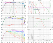
Here are the DSP crossover details (crossover implemented in Minidsp Flex)
The crossover was designed for 20degree off axis as the reference axis (at the height of the CD throat)


Please do provide your comments about this and other things.
Like whether the speakers are supposed to be toed in or not.
Whether that axial 2ish dB low Q bump (from above plot) can be problematic (causing any forwardness in the mids) or not or any other comments/suggestions about improving system performance 🙂
The crossover was designed for 20degree off axis as the reference axis (at the height of the CD throat)
Please do provide your comments about this and other things.
Like whether the speakers are supposed to be toed in or not.
Whether that axial 2ish dB low Q bump (from above plot) can be problematic (causing any forwardness in the mids) or not or any other comments/suggestions about improving system performance 🙂
Why do you have set the drivers impedance to flat: 8 Ohms? You should provide real impedance measurements.
I had not included the impedance response earlier since VituixCAD doesn't use impedance measurements for DSP crossover set up, in which the drivers are directly connected to each amp.
In this case, @WetFartz uses the tube amp to drive the CD horns and a Sabaj A30A Class D amp to drive the woofers. The DSP crossover is implemented on a MiniDSP flex device.
However, I have now included the impedance measurements in the VituixCAD project files and attached to this post 🙂
In this case, @WetFartz uses the tube amp to drive the CD horns and a Sabaj A30A Class D amp to drive the woofers. The DSP crossover is implemented on a MiniDSP flex device.
However, I have now included the impedance measurements in the VituixCAD project files and attached to this post 🙂
Attachments
tbh I am not really a fan of using more than one amplifier for a speaker system. Especially tube amplifiers often have different "tone character" and especially in the crossover region this might come out a bit disharmonic. Whatever, it's your choice ;-)
Personally I would only use the 6080 PSE and a passive x-over (no DSP!) like this with initial component setup (should be further trimmed and an impedance linearization should be added).

Personally I would only use the 6080 PSE and a passive x-over (no DSP!) like this with initial component setup (should be further trimmed and an impedance linearization should be added).
Just iterating over crossover versions. Current crossover in the system


Inspired by @docali's passive crossover, I added few more components into it and it looks like this at the moment 🙂 (I know it is a lot of parts 😀)


Inspired by @docali's passive crossover, I added few more components into it and it looks like this at the moment 🙂 (I know it is a lot of parts 😀)
Attachments
Sounds clean. But we are still fine tuning it, finding the ideal crossover point etc. We might consider a passive CX down the road.
Just tiny bit of component cut down while not compromising much on the power response, PIR and early reflections curve, and also trying to flatten out the impedance of the system above 100Hz.
The CD+horn response is rowdy here. It just eats up crossover components 😀


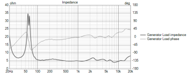
This was one of the main targets. A flatish impedance magnitude response


The CD+horn response is rowdy here. It just eats up crossover components 😀
This was one of the main targets. A flatish impedance magnitude response
Attachments
I would prefer a passive x-over with much less parts accepting a little bit ripple in the fr.
Still working on the theme of component number and component value cut downs 😀
Here is one for today:


Reverse null

With an optional DSP bass boost

Comparison of responses between full analog crossover based system (dotted blue line) and with bass boost (brown). It is going to ask a bit of power from the amp (for that bass boost) but since the system itself has high sensitivty, it should be ok I guess 😀


Here is one for today:
Reverse null
With an optional DSP bass boost
Comparison of responses between full analog crossover based system (dotted blue line) and with bass boost (brown). It is going to ask a bit of power from the amp (for that bass boost) but since the system itself has high sensitivty, it should be ok I guess 😀
This is a very uncommon solution for the bass x-over. A parallel resistor to the woofer is questionable for me. Just use my Zobel from above which equalizes the impedance towards higher frequencies. I have not really any experience with bass reflex designs but imo you should use a notch filter for the right impedance peak of the bass reflex design (single peak devides up into two peaks). And in your latest design you have a phase shift between LF and HF parts.
Passive crossover design has never been my forte.. 😀
Still I have tried to take some suggestions and make a passive crossover version which looks like this now.
I have a few questions


I don't know how a 2dB power response hump around 4.5kHz sounds like..
Looking at the impedance curve above, I am also not sure whether the impedance phase flipping between 1kHz & 3khz is an issue. Ideally I guess a flat impedance is easier on an amplifier but does the above kind of curve look problematic?
Also, I am not sure about the bass response peak notch filtering. In general I am not sure of the path to be taken here..
Requesting help from everyone I know.. 😀
@fluid, @docali , @DonVK, @tmuikku , @hifijim , @tktran303 , @AllenB
Still I have tried to take some suggestions and make a passive crossover version which looks like this now.
I have a few questions
I don't know how a 2dB power response hump around 4.5kHz sounds like..
Looking at the impedance curve above, I am also not sure whether the impedance phase flipping between 1kHz & 3khz is an issue. Ideally I guess a flat impedance is easier on an amplifier but does the above kind of curve look problematic?
Also, I am not sure about the bass response peak notch filtering. In general I am not sure of the path to be taken here..
Requesting help from everyone I know.. 😀
@fluid, @docali , @DonVK, @tmuikku , @hifijim , @tktran303 , @AllenB
Attachments
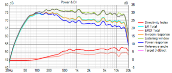
The two sore thumb peaks that stick out, appear in almost all angles the same and stay in the power response. This is a resonance that would be better if it wasn't there. How damaging is it to the sound, I can't say but I would be surprised if you preferred them left in.
When the source is digital, a couple of PEQ's can be applied to remove them, avoiding extra parts in the passive crossover. It can then be easily tested if the resonances are audible and objectionable. This kind of thing can be track dependent, some may sound fine while others really set the resonance going and sound horrible.
When the source is digital, a couple of PEQ's can be applied to remove them, avoiding extra parts in the passive crossover. It can then be easily tested if the resonances are audible and objectionable. This kind of thing can be track dependent, some may sound fine while others really set the resonance going and sound horrible.
I am no expert at passive crossovers, not by a long shot. But it strikes me that your crossover design has a lot of components. Have you tried eliminating some of them? sometimes the effect on the response is minimal after eliminating several components. Never mind, i just read some older posts, and you are already working on this...
I like the nearly flat di curve from 600 to 6k.
I like the nearly flat di curve from 600 to 6k.
Agree... Anything you can do to reduce the resonances at 1.2k and 4.5k would be time well spent.The two sore thumb peaks that stick out, appear in almost all angles the same and stay in the power response. This is a resonance that would be better if it wasn't there.
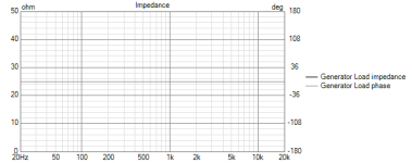
This is it for today. I can't simplify it further. It is a trade-off between frequency response linearity vs impedance vs number of components vs other things. This time the impedance curve has gone up 😀


Reverse null test


WIth some DSP EQ


Also attached with this post are the vituixcad project files for any one who wants to take a look 🙂
Reverse null test
WIth some DSP EQ
Also attached with this post are the vituixcad project files for any one who wants to take a look 🙂
Attachments
Last edited:
- Home
- Loudspeakers
- Multi-Way
- 2-way horn system based on the MK3B2