And the reason why this is supposed to work is that diodes have high "resistance" to low currents and low "resistance" to high currents.
Whether you use 4 or 8 diodes is not really a concern -- the diodes do the same nois duty anyway is my guess. The control of what happens with the ground is far more important.
Petter
Whether you use 4 or 8 diodes is not really a concern -- the diodes do the same nois duty anyway is my guess. The control of what happens with the ground is far more important.
Petter
Powersupply
Hi James,
John Curl uses a 1 or 2 mH choke in place of the diodes D1 & D2 for his powersupply upgrade for the Mark Levinson JC-2 preamplifier. I forgot the exact value.
I tried this too and it works as the sound improved.😉
Hi James,
John Curl uses a 1 or 2 mH choke in place of the diodes D1 & D2 for his powersupply upgrade for the Mark Levinson JC-2 preamplifier. I forgot the exact value.
I tried this too and it works as the sound improved.😉
trwh said:"Also, you should NEVER use diode bridges for audio"
Of course not 🙂
Exactly...
audio is AC anyway! Who needs DC ? The simpler the better 😉
Fedde
This philosophy really works !
Why not omit the transformer and use directly the mains. Or: even better, connect the mains to your speakers ! That's very much bass!!! LOL
Fedde
ps. Do not try this at home. No animals were hurt in the experiment.
Why not omit the transformer and use directly the mains. Or: even better, connect the mains to your speakers ! That's very much bass!!! LOL
Fedde
ps. Do not try this at home. No animals were hurt in the experiment.
fedde said:
Exactly...
audio is AC anyway! Who needs DC ? The simpler the better 😉
Fedde
An AC component present on the amp's DC power supply lines may well modulate the output signal and this can affect the sound. My point was that writing off stanard bridge rectifiers so vehemently was a little over the top. A power supply with a conservatively rated standard 4 diode bridge and the correct capacitative filtering sounds just fine.
Oh, Really?
"John Curl uses a 1 or 2 mH choke in place of the diodes D1 & D2 for his powersupply upgrade for the Mark Levinson JC-2 preamplifier. I forgot the exact value.
I tried this too and it works as the sound improved."
Are you saying an ML preamp has such a poor PSRR that didling with the power supply effects the signal? Considering the price oif those units one would think a buyer could expect siomething better.
BTW: What was the nature of the JC's improvement? Did it lower the noise floor or did it add euphonic artifacts?
Hi,
You can start to doubt by realising that there is no such thing as an "Electron" in reality, but rather a number of quantum particles that on a certain level of understanding appear as "inddivisible" electron while on a different level of understanding you suddenly have several quantum particles having different properties which make up the "current".
So, Electrons are jsut figments of overactive imagination, illusions, so to speak.
Another one of my favourites is that that I always say "Voltage is an illusion".If you start to switch your thinking purely to "current" domain an lot of mysteries become suddenly clear.
Strictly speaking Voltage and Current are two different extremes of viewing the phenomenae "electricity" and really cannot as such be "divided out". But most people these days are so "Voltage" focused that they absolutly do not "get" how important "Current" is in the whole picture.
Another one of the Illusions in electronic (and one that immediatly becomes clear as such when you switch to thinking "current" and "impedance") is the illusion of "ground.
Remember - ground isn't.
I could go on. Virtually all certainties in Electronics are no more than unqualified and undifferenciated prejudices based on 18th to 19th limits of the understanding of Physics.
There is NO HARM in using these convenient short notations for more complex phenomenae, as long as we are carefull not to mistake the illusion for reality.
Within the qualifications of modern physics, yes, absolutely valid. As is Kirchoffs law.
But given that there is NO SUCH THING as Direct Current (DC) in reality (because it would require never to be switched on and never to be switched off - all a question of timescales) the simple view of V, I and R cannot be applied but must be taken complex or we must be aware of the simplifications made to V, I and R when using Ohms Law.
Sayonara
Elkaid said:
Ok !
With all those "strange" suggestions to improve sound (such as connecting resistors or speaker cable "backward", etc.. 🙂 ), I'm beginning to doubt about everything that I took for granted concerning electronics.
You can start to doubt by realising that there is no such thing as an "Electron" in reality, but rather a number of quantum particles that on a certain level of understanding appear as "inddivisible" electron while on a different level of understanding you suddenly have several quantum particles having different properties which make up the "current".
So, Electrons are jsut figments of overactive imagination, illusions, so to speak.
Another one of my favourites is that that I always say "Voltage is an illusion".If you start to switch your thinking purely to "current" domain an lot of mysteries become suddenly clear.
Strictly speaking Voltage and Current are two different extremes of viewing the phenomenae "electricity" and really cannot as such be "divided out". But most people these days are so "Voltage" focused that they absolutly do not "get" how important "Current" is in the whole picture.
Another one of the Illusions in electronic (and one that immediatly becomes clear as such when you switch to thinking "current" and "impedance") is the illusion of "ground.
Remember - ground isn't.
I could go on. Virtually all certainties in Electronics are no more than unqualified and undifferenciated prejudices based on 18th to 19th limits of the understanding of Physics.
There is NO HARM in using these convenient short notations for more complex phenomenae, as long as we are carefull not to mistake the illusion for reality.
(Is ohm's law still valid ?)
Within the qualifications of modern physics, yes, absolutely valid. As is Kirchoffs law.
But given that there is NO SUCH THING as Direct Current (DC) in reality (because it would require never to be switched on and never to be switched off - all a question of timescales) the simple view of V, I and R cannot be applied but must be taken complex or we must be aware of the simplifications made to V, I and R when using Ohms Law.
Sayonara
Hi,
Two Bridges. If you use more than two life becomes interesting.
It's basically one Bridge (or better discrete diodes) per secondary.
My personal recommendation for gainclones BTW is to use two moderatly sized (80VA or so) Torroids per channel, each using full wave rectification with Dual Schottky Diodes to give one single Voltage.
So a 2-Channel "clone" has four transformers, 4pcs Dual Schottky Diodes (and 4pcs of Supply Capacitors).
I just like to use loads of Iron. It works for me.
Sayonara
2Bak said:Something here I'm not sure about:
If one toroid feeds two channels do I need two bridges or four bridges with the above circuit?
Two Bridges. If you use more than two life becomes interesting.
It's basically one Bridge (or better discrete diodes) per secondary.
My personal recommendation for gainclones BTW is to use two moderatly sized (80VA or so) Torroids per channel, each using full wave rectification with Dual Schottky Diodes to give one single Voltage.
So a 2-Channel "clone" has four transformers, 4pcs Dual Schottky Diodes (and 4pcs of Supply Capacitors).
I just like to use loads of Iron. It works for me.
Sayonara
Kuei
What does it mean? A bridge, made of pairs of diodes, or what? What results we should expect? Not that I'm lazy but I should demolish the existing bridges to try.
What does it mean? A bridge, made of pairs of diodes, or what? What results we should expect? Not that I'm lazy but I should demolish the existing bridges to try.
Hi,
Of course not. Full Wave Rectification means full wave rectification. See attached, this shows the configuration of a single of the at least two supplies.
Sayonara
Asen said:Kuei
What does it mean? A bridge, made of pairs of diodes, or what?
Of course not. Full Wave Rectification means full wave rectification. See attached, this shows the configuration of a single of the at least two supplies.
Sayonara
Attachments
why should we use dual diodes instead of single ones?
someone said in this topic, that discrete components are better, since you can match them
someone said in this topic, that discrete components are better, since you can match them
Kuei Yang Wang said:
Two Bridges. If you use more than two life becomes interesting.
It's basically one Bridge (or better discrete diodes) per secondary.
My personal recommendation for gainclones BTW is to use two moderatly sized (80VA or so) Torroids per channel, each using full wave rectification with Dual Schottky Diodes to give one single Voltage.
So a 2-Channel "clone" has four transformers, 4pcs Dual Schottky Diodes (and 4pcs of Supply Capacitors).
I just like to use loads of Iron. It works for me.
Sayonara
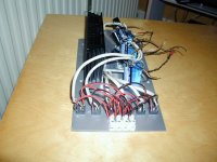
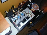
Thanks at lot !! That explains why my fuses keeps blowing when I have more than one chanell hooked up. See pic, where I use six (!) bridges in parallel for three channels. I will try with two bridges only ;-)
/Jan
Attachments
chiily said:Does it fly?
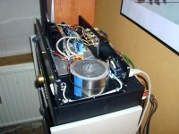
It rocks ! 🙂
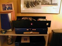
Sound is good. I am gonna use this three-channel as amp for surround and center speakers.
Details: This circuit. MU metal around toroid, 300VA. LM3875T. No special components. Roedenstein film caps, normal metal films. Standard 1000uF caps. Caddock 0,2 in output.
Case is from an old tube pre-amp, Audio Innovations

Attachments
Burning you bridges behind you
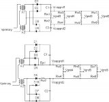
At the risk of further confusion I thought I would jump off... um actually into; the great bridge debate. First off is the ground is used as a references to the other voltages on a schematic and the ground paths seldom show in detail on most schematics. the large charging currents from then transformer secondariness mean the even return wiring resistance of a few milliohms can result in significant voltages between the ground reference for input cable ground, speaker return grounds, filter capacitor grounds, and amplifier input and feedback ground points.
Referencing the top figure in the schematic included: the wiring resistances for the return path between the transformer secondary center tap and the filter caps ground terminals are given as Rw1 for filter C1 and Rw2 for filter C2. As the charging current to the filter caps is returned through the wiring resistance Rw1 and Rw2 a voltage is developed between the capacitor ground terminals that is given by Vcapgnd1 - Vcapgnd2. This voltage appears the across resistances for the ground returns described above as given by Rw3 though Rw8 as the ration for return resistances Rw3/ Rw3 to Rw7/Rw8 can easily differ from unity and the various ground reference voltages given by Vgnd3 to Vgnd6 will be at different voltages due to the Vcapgnd1 - Vcapgnd2 drop across the unequal resistances Rw3 to Rw8.
A thick plate of a low resistance material is often used to tie these ground returns together and minimize the ground return resistances. I worked on a BandK amp where ground return wires contained ring terminals that were connected to the chassis with a large screw and nut. The order in which these terminals were placed on this screw made a difference in the measured 120Hz noise at the outputs.
Referencring to the bottom figure on the schematic of the two bridge circuit, it is seen that the return currents through rw1 and Rw2 are galvanically isolated by the seperate secondary windings. Thecapacitor charging currents do return not return through the the series combination of Rw1 and Rw2 so that the Vcapgnd1 - Vcapgnd2 drop due the charging current is zero. Either method will work but the single brige requires much greater attention to the ground return path. Hopefully this shred some light into why getting the hum out of an amp requires close attention to the grounding scheme. Hopefully it will also help to explain single point grounding and the use of transformers to isolate ground loops. More likely that it will get me thrown back into the sin bin.
Attachments
BUT FRED...
Hi,
Why would that be?
This same topology I use in OTL amps, it does make a lot of sense to me.
Nice work,😉
Hi,
More likely that it will get me thrown back into the sin bin.
Why would that be?
This same topology I use in OTL amps, it does make a lot of sense to me.
Nice work,😉
- Status
- Not open for further replies.
- Home
- Amplifiers
- Chip Amps
- 2 Rectifier bridges : Why ?