Interesting conclusion, considering this the next day......So, this project is now a Deed Duck!!
Cheers
I would rather agree with DNic's message above - even the project is at Github, but code is missing. How to build firmware without a source code?
I wanted to ask for the firmware for this project, and realized that I couldn’t send a PM in any way. Nice. 🤣
Same with me. Could you share your experience afterwards?I wanted to ask for the firmware for this project, and realized that I couldn’t send a PM in any way. Nice. 🤣


Following a very good enquiry, I've added details to the first post about the additional library required for rotary encoder use, namely https://github.com/brianlow/Rotary
In my latest raft of PCBs about to be sent off, I thought I'd put together a version that better supports three phase applications in a single board, rather than the previous 'stack'.

This can be used with either Nano or Uno. As a member had successfully modified the code to use an I2C OLED diaply, there is an additional connector for this, and support has been added to the code ready for the next release. As usual, I will release the Gerbers once tested.
This can be used with either Nano or Uno. As a member had successfully modified the code to use an I2C OLED diaply, there is an additional connector for this, and support has been added to the code ready for the next release. As usual, I will release the Gerbers once tested.
Do I understand that the next release will include code for I2C OLED display? if so that's welcome news. Cheers.
So far I've been driving a 24v AC synchronous motor using a simple amplifier, but I still had the original premotec 110v AC synchronous motor from my turntable, and I've always been intrigued by an example in Horowitz and Hill of driving such a motor using feedback from the step-up transformer high voltage output rather than just using a fixed gain amplifier to drive the low voltage input. I realise that this may come under the catogory of 'fixing a problem that doesn't exist', but hey this is DIY and it could be an interesting exercise.....
For this, we want to take feedback from the transformer output around the frequencies of interest (50 and 67.5Hz), i.e. with a bandpass characteristic, but need to take LF feedback (for low DC offset to the transformer) and HF feedback (for stability) directly from the opamp output, i.e. with a band-reject characteristic. This is implemented in the following circuit, using a transformer measured as requiring a 5v AC RMS input to generate the 110v AC RMS output:

Simulating the feedback network gives the following contributions to the feedback signal:

The RED line shows the overall bandpass characteristic from the transformer output, and CYAN is the overall band-reject characteristic from the opamp output (with YELLOW and GREEN being the individual lowpass and highpass characteristics). This was set to cross the RED line at just over a decade away from the desired frequencies, such that the majority of the feedback is then from the transformer output.
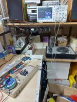
This has been prototyped (unfortunately one of the transformers I ordered had a shorted winding, so initially I'm having to use only one channel with the original motor phase network):

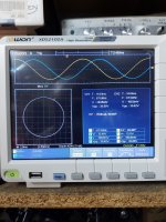
Measured opamp and transformer output at 50Hz (motor running):

I measured the fequency response at both the opamp and transformer outputs, and although having to use only one phase plus the motor phase network may give slightly unrealistic load away from the nominal 50Hz, it shows the amplitude control transferring between the transformer and opamp outputs as desired.

I now need to get a second transformer with my next component order in order to fully test it when driven by a 2-phase generator (and maybe reduce to LF cut-on freqency of my mesurement interface too).
For this, we want to take feedback from the transformer output around the frequencies of interest (50 and 67.5Hz), i.e. with a bandpass characteristic, but need to take LF feedback (for low DC offset to the transformer) and HF feedback (for stability) directly from the opamp output, i.e. with a band-reject characteristic. This is implemented in the following circuit, using a transformer measured as requiring a 5v AC RMS input to generate the 110v AC RMS output:
Simulating the feedback network gives the following contributions to the feedback signal:
The RED line shows the overall bandpass characteristic from the transformer output, and CYAN is the overall band-reject characteristic from the opamp output (with YELLOW and GREEN being the individual lowpass and highpass characteristics). This was set to cross the RED line at just over a decade away from the desired frequencies, such that the majority of the feedback is then from the transformer output.
This has been prototyped (unfortunately one of the transformers I ordered had a shorted winding, so initially I'm having to use only one channel with the original motor phase network):
Measured opamp and transformer output at 50Hz (motor running):
I measured the fequency response at both the opamp and transformer outputs, and although having to use only one phase plus the motor phase network may give slightly unrealistic load away from the nominal 50Hz, it shows the amplitude control transferring between the transformer and opamp outputs as desired.
I now need to get a second transformer with my next component order in order to fully test it when driven by a 2-phase generator (and maybe reduce to LF cut-on freqency of my mesurement interface too).
The v3 board and v4.4 firmware have now been tested and are available.
v3 board new features:

v4.4 firmware new features:
Also, in order to improve the power-on transients, the start-up has been adjusted to first allow settling of the circuitry, followed by an initial ramp of the PWM to the 50% 'off' state. To support this, it is recommended to change the resistors R1 and R2 to 100k (were 10k).
The first post has been updated, with latest Gerbers and schematic.
v3 board new features:
- can be used with Arduino UNO or Nano
- all 3 phases available on single board
- SPI or I2C OLED support
v4.4 firmware new features:
- SPI or I2C OLED support (SSD1306)
- selectable soft-start time (0, 2s, 1s, 0.5s, 0.25s)
- can specify clock frequency, to compensate sinewave frequency and tachometer for actual oscillator frequency (measure sinewave frequency to calculate offset)
Also, in order to improve the power-on transients, the start-up has been adjusted to first allow settling of the circuitry, followed by an initial ramp of the PWM to the 50% 'off' state. To support this, it is recommended to change the resistors R1 and R2 to 100k (were 10k).
The first post has been updated, with latest Gerbers and schematic.
Greetings,
I joined a year ago but this is my first post. I have been active in restoration of vintage Audio for some time. I wanted to say Thank You for the amazing information the members provide on here.
I have a specific question related to the 2 Phase Driver board in this thread. I have a Pro-Ject Signature 12 Table that I need to get back up running. The factory Touchpad/Microcontroller Board died. Pro-ject is no longer supporting this table. They are willing to sell me an entire new board but the price is $1500 USD!
The motor amplifier section is operating, so via my function generator, I can drive the table. I have also determined the Frequencies for 33/45 RPM that achieve the required speeds. (Motors are 16VAC Synchronous)
My question is, are these boards and software still available? It looks like the perfect match for what I am needing.
Thank you for letting me rant and for the support!
Kevin
Follow-up, I should have read more ad typed less. Everything I need was right in front of my eyes.
I will reach out to RichB for the FW.
If you will allow me one question which I did not find an answer in this thread: My turntable is not Direct Drive but uses several pulleys. Can I use a custom frequency setting for 33 and 45R PMs? For example, I would need a center frequency of 41.45Hz for 33RPM.
Kevin
The latest boards and FW should work fine for your application (and come in a bit under $1500!). The alternative frequency you quote will be no problem, we can catch up via PM for the firmware and options.
I'm a little behind in updating the build guide for the latest board iteration, so this is a good prompt for me to get that done.
I'm a little behind in updating the build guide for the latest board iteration, so this is a good prompt for me to get that done.
Rich,
I wanted to say Thank You for all the tremendous support you have been giving me “behind the scenes “! Your design has helped me resurrect my favorite turntable back to working order.
You represent all that is good in the DIYAudio community!
Kevin
I wanted to say Thank You for all the tremendous support you have been giving me “behind the scenes “! Your design has helped me resurrect my favorite turntable back to working order.
You represent all that is good in the DIYAudio community!
Kevin
- Home
- Source & Line
- Analogue Source
- 2 phase synthesised sinewave generator for synchronous motor drive