This is a shared DIY project, for non-commercial use. It consists of a PCB and firmware for the chosen processor module:
17-Mar-25 firmware update correcting negative phase saving error, see here
09-Dec-24 firmware update adding frequency-dependant amplitude feature, see here
29-Oct-24 firmware update adding frequency ramp feature, see here
25-July-24 PCB updated to v3.1, minor footprint updates but no change in functionality, see here
14-Jun-23 new PCB v3.0_PICO for Raspberry Pi Pico, see here
04-May-23 update to RP2040 processor, compatible with Nano PCBs, see here
This is the sinewave generator only, and will require amplifying to the target motor's voltage. A 2 or 3 channel amplifier is needed to either directly drive a low voltage motor, or line level motors via suitable step-up transformers. (A low voltage amplifier for driving a 24v 2 phase synchronous motor is detailed here).
Gerber files for the latest PCB and build guide are attached to this post.
The latest firmware release for all supported RP2040 modules is now available at:
https://drive.google.com/drive/folders/1zttD3h1yLh_rkOKi_ILMN6ePMEPL9Dlp?usp=drive_link
The original Uno/Nano processor/firmware is retired and no longer supported. However, those with existing v3.0 and v2.0_NANO PCBs can still use them with the RP2040 processor/firmware, configured according to the latest build guide.


Some example waveform profiles:


- 2 (0, 90°) or 3 (0, 120°, 240°) phases of sinewave generation, with electronic speed switching between 33 or 45rpm
- optional tachometer, with configurable pulses-per-rev and averaging (requires external sensor providing logic level pulses)
- OLED display (SSD1306, SPI or I2C)
- buttons or rotary encoder support for stop/start, speed switching, frequency/phase adjustment and menu operation
- selectable soft start amplitude or frequency ramp, to support different motor types and setups
- selectable delayed reduced amplitude, separate settings for each speed
- configurable frequency-dependant-amplitude to maintain constant current/torque at different speeds
- menu system for all settings with live adjustments, saved in non-volatile memory
- RP2040 processor based module with easy drag-and-drop firmware upload
17-Mar-25 firmware update correcting negative phase saving error, see here
09-Dec-24 firmware update adding frequency-dependant amplitude feature, see here
29-Oct-24 firmware update adding frequency ramp feature, see here
25-July-24 PCB updated to v3.1, minor footprint updates but no change in functionality, see here
14-Jun-23 new PCB v3.0_PICO for Raspberry Pi Pico, see here
04-May-23 update to RP2040 processor, compatible with Nano PCBs, see here
This is the sinewave generator only, and will require amplifying to the target motor's voltage. A 2 or 3 channel amplifier is needed to either directly drive a low voltage motor, or line level motors via suitable step-up transformers. (A low voltage amplifier for driving a 24v 2 phase synchronous motor is detailed here).
Gerber files for the latest PCB and build guide are attached to this post.
The latest firmware release for all supported RP2040 modules is now available at:
https://drive.google.com/drive/folders/1zttD3h1yLh_rkOKi_ILMN6ePMEPL9Dlp?usp=drive_link
The original Uno/Nano processor/firmware is retired and no longer supported. However, those with existing v3.0 and v2.0_NANO PCBs can still use them with the RP2040 processor/firmware, configured according to the latest build guide.
Some example waveform profiles:
Attachments
Last edited:

fatastic sharing,what is the voltag for the OPA2134,does the OPA2134 drive the Moto directly or need another amp board to dirve the MOTO?
from the sup-a-spin screen short,I saw the +0.01 and -0.01,does it means frequence can be adjust 0.01Hz,is that correct?
thanks.
Leo
from the sup-a-spin screen short,I saw the +0.01 and -0.01,does it means frequence can be adjust 0.01Hz,is that correct?
thanks.
Leo
If you mean the voltage at the output of the OPA2134, I have set the LF gain to 3.3k/12k = 0.275, so that the 5v p-p PWM from the Arduino gets translated to a 1.375v p-p sinewave at the output of the OPA2134, centred around 2.5v. The ac-coupling at the output removes this DC offset.fatastic sharing,what is the voltag for the OPA2134,does the OPA2134 drive the Moto directly or need another amp board to dirve the MOTO?
from the sup-a-spin screen short,I saw the +0.01 and -0.01,does it means frequence can be adjust 0.01Hz,is that correct?
thanks.
Leo
This cannot drive the motor directly, so needs to be amplified up to the required voltage for the motor, which I measured at about 50v p-p, and for this I use a regular integrated amplifier (in my case an old Rotel RA-840 in which I have fixed the preamp gain in order to give 50v p-p at the outputs at full volume).
Yes I have chosen fine-tuning increments of 0.1 and 0.01Hz, whcih translate to <0.01rpm increments.
Dear Rich,I do not have the RemoteXY Pro,so I have an idea thtat use the ecoder or buttons to replace your RemoteXY button,+0.01,-0.01 for the Frequency and phase adjust button + and - button function, so I have some question for the arduino soure code,would you please give me more information.
1.what is the function for? convert to RPM or other?
unsigned long frq2phinc (uint16_t frq) {
return (((unsigned long) frq * hz2phinc + 50) / 100);
}
2. what means for the cHz
uint16_t freq33 = EEPROM.read(EEADDR_frq33) + (EEPROM.read(EEADDR_frq33+1) * 100); // cHz
3. please share more information for the indexA and indexB
ISR(TIMER2_OVF_vect) {
uint16_t indexA = phase>>nrFracBits;
uint16_t indexB = (indexA + (1<<(LUTbits-2)) + (phadj_sel * 3)) % (1<<10);
phase += phinc_sel;
4. phinc_sel and freq_sel means the user select frequency and phase.right
you help will be grep apprecate.
1. The function returns the value that needs to be added to the 32bit phase accumulator on every Timer2 interrupt which occurs every 31.875µSec. The constant hz2phinc was calculated just prior (136902) and is the value needed for 1 Hz. frq2phinc(frq) passes the frequency value which will be 5000 for 50.00 Hz and is multiplied by 136902 and divided by 100 to give the correct value for the amount of phase increase on each Timer2 interrupt. 50 is added to round up the LSB.
2. cHz is centiHertz. The running frequency is stored in 2 EEPROM locations, one for the integer part and one for the decimal part. 50.25 Hz would be stored as 25 and 50; after the calculation, freq33=5025 cHz as is needed by the function frq2phinc.
3. phase is the 32 bit phase accumulator; phase>>nrFracBits returns the upper 10 bits of the phase accumulator and is used as the index into the sinewave table. 1<<(LUTbits-2) adds 90° (+256) and phadj_sel*3 adds 1.0546875° for each count in phadj33 or phadj45 (360°/2^10)*3. IndexA and IndexB are used to look up the values needed for the sine and cosine outputs on each sample period (31.875µSec). %(1<<10) is modulo 1024 and returns a 10 bit value.
4. freq_sel and phadj_sel are the user selected frequency*100 and user selected phase offset (-15°~+15°). phinc_sel is the user selected value that is added to the phase accumulator every 31.875µS (510 instruction cycles).
@Rich- Love the user interface!
Last edited:
Awesome, thanks @Pyramid, I'm sure you expressed it better than I would have! And for some sort of sanity check on my code 🙂
Since using the RemoteXY app, I use it quite often for a quick and flexible user interface, only having to connect the BT module rather than a display and buttons etc.
@Adams_Leo, I only added the physical button for start/stop at the end of the development, but I think it would be useful to add provision for tuning buttons too, so I'll update and repost the code for this, hope that helps
1. The function returns the value that needs to be added to the 32bit phase accumulator on every Timer2 interrupt which occurs every 31.875µSec. The constant hz2phinc was calculated just prior (136902) and is the value needed for 1 Hz. frq2phinc(frq) passes the frequency value which will be 5000 for 50.00 Hz and is multiplied by 136902 and divided by 100 to give the correct value for the amount of phase increase on each Timer2 interrupt. 50 is added to round up the LSB.
2. cHz is centiHertz. The running frequency is stored in 2 EEPROM locations, one for the integer part and one for the decimal part. 50.25 Hz would be stored as 25 and 50; after the calculation, freq33=5025 cHz as is needed by the function frq2phinc.
3. phase is the 32 bit phase accumulator; phase>>nrFracBits returns the upper 10 bits of the phase accumulator and is used as the index into the sinewave table. 1<<(LUTbits-2) adds 90° (+256) and phadj_sel*3 adds 1.0546875° for each count in phadj33 or phadj45 (360°/2^10)*3. IndexA and IndexB are used to look up the values needed for the sine and cosine outputs on each sample period (31.875µSec). %(1<<10) is modulo 1024 and returns a 10 bit value.
4. freq_sel and phadj_sel are the user selected frequency*100 and user selected phase offset (-15°~+15°). phinc_sel is the user selected value that is added to the phase accumulator every 31.875µS (510 instruction cycles).
@Rich- Love the user interface!
wow.supper,clear and fully understand,really appreciate,Sir.
Awesome, thanks @Pyramid, I'm sure you expressed it better than I would have! And for some sort of sanity check on my code 🙂
Since using the RemoteXY app, I use it quite often for a quick and flexible user interface, only having to connect the BT module rather than a display and buttons etc.
Your code is very well organized and fairly easy to follow.
I had a thought: If you separated the timer function from the PWM output you could use a 20bit phase accumulator and greatly simplify the code. If you used Timer1 with an overflow value of 1526, it will create a 10,484.928 Hz clock; with a 20 bit accumulator, the frequency resolution is 9.9992mHz (~0.01Hz). You can implement a 20bit accumulator by using an unsigned long variable and shift everything to the left <<12. If frq_sel=5000, then phinc_sel=frq_sel<<12. Your PWM output is only 8 bits, so you could shrink the table down to 256 entries; IndexA=phase>>24 and IndexB=(phase>>16 + 16,384 + phadj_sel*182) >>8. Your phase step is ~0.99975°/count in phadj_sel.
Timer2 still runs at ~31kHz, but interrupts are disabled; OCR2A and OCR2B still create the 8 bit PWM outputs.
I work almost exclusively in assembly language and I'm always looking for ways to simplify the math and reduce the number of calculations. Just my 2p.
Thanks for the pointers @Pyramid, much appreciated, I dare say there's some arithmetic optimisation to be had, I defaulted to the maximum fixed point precision using 32-bit integers, and was happy I managed to code it fully in fixed point arithmetic and not fall back on floats! Maybe as an exercise I will make these improvements when I've run out of other projects 🙂Your code is very well organized and fairly easy to follow.
I had a thought: If you separated the timer function from the PWM output you could use a 20bit phase accumulator and greatly simplify the code. If you used Timer1 with an overflow value of 1526, it will create a 10,484.928 Hz clock; with a 20 bit accumulator, the frequency resolution is 9.9992mHz (~0.01Hz). You can implement a 20bit accumulator by using an unsigned long variable and shift everything to the left <<12. If frq_sel=5000, then phinc_sel=frq_sel<<12. Your PWM output is only 8 bits, so you could shrink the table down to 256 entries; IndexA=phase>>24 and IndexB=(phase>>16 + 16,384 + phadj_sel*182) >>8. Your phase step is ~0.99975°/count in phadj_sel.
Timer2 still runs at ~31kHz, but interrupts are disabled; OCR2A and OCR2B still create the 8 bit PWM outputs.
I work almost exclusively in assembly language and I'm always looking for ways to simplify the math and reduce the number of calculations. Just my 2p.
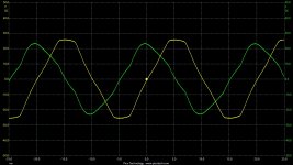
As for the lookup table size, I had an argument for using 1024 rather than 256 points:
At my lowest frequency of 50Hz, the phase advance per sample period (31.875us) is 360*31.875u/(1/50) = 0.57375 degrees. This is equivalent to 360/0.57375 = 627 points per period.
Hence having a 256 points per period lookup table, the table index would only advance (256/627) = 0.408 steps per sample on average, giving fairly coarse time quantisation, leading to some amplitude quantisation.
Going up to 1024 points per period, the table index would advance (1024/627) = 1.632 steps per sample on average, giving both finer time quantisation, and less amplitude quantisation, also due to finer Y resolution of the table.
I've pushed my Excel skills to demonstrate this, as shown in the picture, where the smoother blue curve for 1024 ppp relative to that for 256 ppp in orange can be seen. Hope it is fathomable!
Attachments

Updated Arduino code with additional pushbuttons:
frequency +0.01Hz on pin A1
frequency -0.01Hz on pin A2
phase +1 on pin A3
phase -1 on pin A4
(I'm not sure if I can change the attachment in the first post)
frequency +0.01Hz on pin A1
frequency -0.01Hz on pin A2
phase +1 on pin A3
phase -1 on pin A4
(I'm not sure if I can change the attachment in the first post)
if I only need single phase sine wave,only modifiy like this right?
ISR(TIMER2_OVF_vect) {
uint16_t indexA = phase>>nrFracBits;
// uint16_t indexB = (indexA + (1<<(LUTbits-2)) + (phadj_sel * 3)) % (1<<10);
phase += phinc_sel;
byte readA = pgm_read_byte(&sinewave_data[indexA]);
// byte readB = pgm_read_byte(&sinewave_data[indexB]);
OCR2A = readA;
//OCR2B = readB;
}
ISR(TIMER2_OVF_vect) {
uint16_t indexA = phase>>nrFracBits;
// uint16_t indexB = (indexA + (1<<(LUTbits-2)) + (phadj_sel * 3)) % (1<<10);
phase += phinc_sel;
byte readA = pgm_read_byte(&sinewave_data[indexA]);
// byte readB = pgm_read_byte(&sinewave_data[indexB]);
OCR2A = readA;
//OCR2B = readB;
}
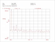
There is a slight improvement over an 8 bit table, but I think the reconstruction filter will remove most if not all of that. The SG4 uses 8 bit PWM with 256 table entries and the 3rd harmonic is ~-51dBc where yours is ~-63dBc? The SG4 has a 2 pole LPF with an Fc of 230Hz; the sampling frequency is also quite a bit lower: 209.7 samples/cylce vs 627 samples/cycle on yours. I think for motor drive applications, this is perfectly acceptable.
I also think you could still use a 10bit LUT with the 20bit phase accumulator; the sampling frequency will be lower (10kHz vs 31kHz), so it would be interesting to see if there was a difference in performance.
For comparison, the VPI SDS used a 3 bit DAC (8 output levels) and 16 samples/cycle. After their 2 pole LPF, distortion was still only 0.2% (their LPF had an Fc of 190Hz IIRC).
Attachments
Yes, just commenting the last line you show, //OCR2B = readB, will stop updates to this channel and leave it in the 'idle' state of 50:50 PWM (this maintains the DC level at the output and prevents a DC settling transient on each start/stop).if I only need single phase sine wave,only modifiy like this right?
ISR(TIMER2_OVF_vect) {
uint16_t indexA = phase>>nrFracBits;
// uint16_t indexB = (indexA + (1<<(LUTbits-2)) + (phadj_sel * 3)) % (1<<10);
phase += phinc_sel;
byte readA = pgm_read_byte(&sinewave_data[indexA]);
// byte readB = pgm_read_byte(&sinewave_data[indexB]);
OCR2A = readA;
//OCR2B = readB;
}
Or more directly, you could disconnect the chosen pin from the PWM generator by changing the line
TCCR2A = (1<<COM2A1) | (1<<COM2B1); // clear on Compare Match
to
TCCR2A = (1<<COM2A1); // clear on Compare Match
That's great that you got it working!
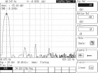
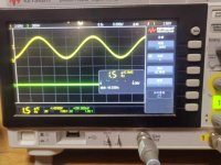
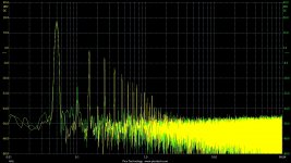
I'm totally with you, all these solutions are way better than what I measured from the default 'wall wart' AC PSU (which most would be happy with), as shown below 😱,There is a slight improvement over an 8 bit table, but I think the reconstruction filter will remove most if not all of that. The SG4 uses 8 bit PWM with 256 table entries and the 3rd harmonic is ~-51dBc where yours is ~-63dBc? The SG4 has a 2 pole LPF with an Fc of 230Hz; the sampling frequency is also quite a bit lower: 209.7 samples/cylce vs 627 samples/cycle on yours. I think for motor drive applications, this is perfectly acceptable.
I also think you could still use a 10bit LUT with the 20bit phase accumulator; the sampling frequency will be lower (10kHz vs 31kHz), so it would be interesting to see if there was a difference in performance.
For comparison, the VPI SDS used a 3 bit DAC (8 output levels) and 16 samples/cycle. After their 2 pole LPF, distortion was still only 0.2% (their LPF had an Fc of 190Hz IIRC).
The main advantage for me of running at the maximum PWM rate, is to give the maximum frequency difference between the sinewave and PWM rate, which allowed use of a simple single-pole LPF high enough above the tone, but still give good attenuation at the PWM rate (plus in my case, as I'm amplifying using a normal integrated amp, I can get further PWM attenuation using the treble tone control).
Attachments
Following on from your suggestion, with a minor code tweek I've emulated various LUT sizes, giving the following results for 2/4/6/8/10 bits. Interesting! Very little gained from 8->10 bits as you suggested.
Attachments
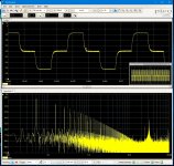
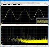
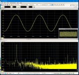
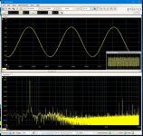

Interesting, thanks for the charts.
If you do go to a 10kHz sample rate from your current 31kHz, I think you will need to use a 2 pole filter on the output. Your current filter is -36dB at 31kHz; at 10kHz it will only be -27dB. The 2 pole filter on the SG4 is down -63dB at 10kHz with Fc=230Hz.
If you do go to a 10kHz sample rate from your current 31kHz, I think you will need to use a 2 pole filter on the output. Your current filter is -36dB at 31kHz; at 10kHz it will only be -27dB. The 2 pole filter on the SG4 is down -63dB at 10kHz with Fc=230Hz.
Correction on post #18: The sample rate of the SG4 is 10kHz but the PWM frequency is 18kHz; at 18kHz the response of the 2 pole filter is -75dB. If you went with a 10kHz sample rate, the PWM frequency would still be 31kHz and the response with a 2 pole filter would be -85dB.
I'm impatient to try this generator so I am trying to load the code before I have the filters built. I have the HC-06 connected as shown in your schematic, including the 4.7K and 10K resistors connected to Gnd and the TX pin. The sketch compiles normally but I'm getting an error when loading:
"avrdude: stk500_getsynch 1 of 10: not in synch"
Get this message 10 times then
"avrdude: stk500_recv(): programmer not responding"
I'm not astute enough with Arduino to know what I'm doing wrong. Any suggestions will be appreciated.
"avrdude: stk500_getsynch 1 of 10: not in synch"
Get this message 10 times then
"avrdude: stk500_recv(): programmer not responding"
I'm not astute enough with Arduino to know what I'm doing wrong. Any suggestions will be appreciated.
- Home
- Source & Line
- Analogue Source
- 2 phase synthesised sinewave generator for synchronous motor drive