Hello everyone. I'm really enjoying getting back into this, and all of your help. I was wondering if you wouldn't mind sharing some of your tried schemes for a 2 octals splitter/driver combination. I'm going to be driving KT88 or 6550, and have around 500V B+, -85v bias to utilize. I'm seeing a lot of similar things here lately, but with 9pin tubes, and didn't want to hijack a thread. I'd really like to have some current behind my drive this time around. I've thought about 6sn7/sl7 combinations, cathode followers or mosfet followers, but I figured it was silly not to ask and see some of what you all have come up with.
Thanks much- Loren
Thanks much- Loren
Pick the topology first, not the tube.
It seems that you need +/- 85V per phase. That is a lot of swing.
First, decide if you will do a combination splitter/driver as one stage.
For that, an LTP gives 1/2 the gain of a paraphase splitter/driver.
Hard to get +/- 85V out of an LTP splitter/driver.
So, for just one stage a Paraphase splitter/driver (even that will be difficult to get the required swing, at low distortion).
Or, use an LTP splitter, and then add another stage after that for gain to get the +/- 85V.
Two stages.
A concertina (split load) phase splitter is not going to give two phases that each have +/- 85V;
So you need a gain stage, then a concertina splitter, then another gain stage.
Three stages.
I will not speak to the use of JFETs or MOSFETs in the signal path of a tube amplifier.
I am sure others will have ideas of the best topology.
Then work on what tubes will fill the bill.
Just my opinions.
Have fun designing, building, and listening!

That's my favourite combination, 6SN7 for LTP, DC-coupled to a 1/2 6SL7 input stage. The LTP tail can be a CCS to balance it, or just a resistor and adjusting the plate loads.I've thought about 6sn7/sl7
When you say DC coupled I think you mean the other side of the LTP with a high value resistor from the first plate and a cap to ground.
6a3summer- thank you. I should have specified, I have -85 but I will probably have somewhere around -65 to the grids. I might have a good bit less actually, if I do mixed bias which I'd like to try, but 65v is probably closer to my drive requirement. Although of course, headroom is important.
And yes I should have pinpointed a topology, I was just curious what some others have done. I had figured I would be stuck with either amplifying the signal before, or after, a LTP. I think I would also choose the former, and that was what I meant about circuits using 6sn7/sl7. But the ability to have some drive current would be nice, so I was curious if anyone had worked up anything with just 2 octal tubes, where the second had some current to feed. This is where I thought of 6bx7. And again I'm just trying to wrap my head around more, and seeing schematics, thinking about what values are what they are, helps a lot. I don't see much at all online in this aspect, save from the 6sn/l7 circuits discussed.
Thank you all 🙏
Loren
DC coupled to the input stage. AC-coupled to the output tubes:When you say DC coupled I think you mean the other side of the LTP with a high value resistor from the first plate and a cap to ground.
I have used it with 6P3S-E outputs, and also simulated it with both 6L6 and KT88s.
I borrowed it from the EICO-89.
I borrowed it from the EICO-89.
Thanks JC, thanks baudouin0. I hope to have a weekend sometime soon to check out ltspice more. I gave it 3 hours or so the other night, but was struggling to do a few basic things. Especially being on a Mac.
Yes this looks just like one of the 6SL7/6sn7 circuits I imagined. I would definitely want to use my negative voltage for the tail though, if not for the simple fact I have not done this in any prior projects.
Baudouin0- why did you change the bootstrapping (that's what it's called, right?) R5 from 1M to 470k in the sim? I see some other changes too, which I understand for ease of use in your end. But what is the purpose of the extra RC decoupling R21 and C7, and how is that equated?
Thanks much as always, this helps a lot just getting me thinking on it...
Self Bias; Fixed Bias; Adjustable Fixed Bias; and Mixed Bias output stages.
The driver has to swing both + and - Voltages equal to the Total Bias Voltage, including when using Mixed Bias.
Mixed Bias does Not reduce the driver swing requirements.
Driver Current is required for these things:
Miller Effect Capacitance
Grid resistor RG
Grid current if you are going to use a Class A2, AB2, etc. circuit. . . . (Any 2, such as B2, etc.)
RC coupling does not work well with any grid current.
The Miller Effect current is larger in Ultra Linear mode; Versus True Pentode mode, and True Beam Power modes.
Have Fun!
Last edited:
6a3sUMMER- Thank you. I need to go back and edit that for clarity. I do know that the bias voltage is doubled (in rms), and then some for the drive requirement. I wanted to convey that I think my actual bias points will not be that entire -85 I have available. And with a few changes to my current design, I think I can get the B+ down closer to 450, which would put me even less -65 on the grids.
And thank you for the reminder about drawing Ching grids positive. This is why I was wondering if anyone had ever done anything with a higher gain tube, because if I had say something direct coupled to a concertina, I could use the other tube (6sn7) as cathode followers.
Thanks all of you again. I'll be back in a day or two with something drawn up. I have used the ltp with great success before, I like the balance, and the 6SL7>6SN7 ltp circuit would give me the needed gain, especially at the lower voltage points. I'm going to try to come up with something using followers still, and I'll throw it up here when I do
Loren
Hi again everyone. Ive got most of the schematic drawn up, but I'm running into one issue. I've never done a long tailed pair direct coupled to the previous stage, and I feel like I'm missing something. When I draw load lines for either of your circuits, or what I'm coming up with, the 6sn7 sections are biased around -10v. And that makes sense, Id want them biased somewhere close to the center of the range. But in both of your circuits, the voltage measurements given put the grid only about 4v negative of the cathode. With say a concertina direct coupled, I'd just figure out the cathode resistor to give me X many volts more, than the previous stage plate, hence my bias. What am I missing here?
Thanks, I'm looking forward to showing you. I got taken away by work for a few days but I feel close now.
Edit: I think I just answered my own question, I was just looking at the wrong point on the load line, considering that cathode voltage changes Va-k. I'll finish this up and show y'all
Thanks, I'm looking forward to showing you. I got taken away by work for a few days but I feel close now.
Edit: I think I just answered my own question, I was just looking at the wrong point on the load line, considering that cathode voltage changes Va-k. I'll finish this up and show y'all
Last edited:
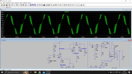
Alright, I do think this will work. It was nice having a little more voltage to work with than the above schematics, but obviously they're all very similar. Short of learning LT spice, I think this will get me to where I can measure and see for myself.
Thank you all again for you help and input on this,
Loren
Thank you all again for you help and input on this,
Loren
Attachments
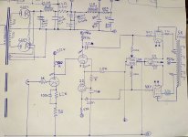
Almost there 🙂 . You need to add a grid leak resistor to the input triode.
And probably you will need some negative feedback from the output transformer to the first stage.
And probably you will need some negative feedback from the output transformer to the first stage.
I was going to mention that, sorry, but yeah I left some things omitted for simplicity. The grid leak, the feedback. I'm still curious about Baudouin0's RC network off of the plate of the 6sl7 to dominate the pole, and possibly, power drive fets before the KT88's just because I want to be confident in using them.
Thank you JC, and thank you all of you 🙏,
Loren
Thank you JC, and thank you all of you 🙏,
Loren
Bias Pots that do not have a fixed resistor from the wiper to the most negative end of the Pot, are dangerous.
If the wiper makes a bad contact, the KT88s die.
If the wiper makes a bad contact, the KT88s die.
Its not mine its quite standard the RC across the plate for HF stability but only required with GNFB. The only thing that's slightly unusual is the LF circuit around C6. This is better than the usual arrangement as it causes the open loop gain to raise at 1-5Hz which is lead compensation. This prevents LF instability. You currently have 3 LF poles - the OPT, the coupling to the KT88's and although you may think your DC coupling the LPT, the differential gain is zero for DC with the rolloff caused by the 470K and 470n as the second grid catches up with the first.
Other than that your circuit is quite standard which is a good thing.
Other than that your circuit is quite standard which is a good thing.
Last edited:
- Home
- Amplifiers
- Tubes / Valves
- 2 Octal splitter/driver combinations for KT88 amp