Yep adding a 220k from the wiper centre to the neg rail is good.
Maybe a grid series resistor on the LPF second grid with that 470nF to ground. If it was a e88cc I would be concerned about VHF oscillation but a 6SN7 I have not used - looks quite non RF'y.
Other thing to watch is the LPT plate voltages when the tubes are cold. You may wish to bleed some of the supply - worth checking the data sheet.
Thank you both, good point on the wipers. I know better too, things like the grid resistors I just wasn't concerned with, but I should have put those in. Will do, and then all of these points, and re-draw it.
I do realize the plate voltage would be pushing it, although I'm quite sure I'd still get away with it with vintage tubes...but everything is on a slow warm up, and the 6SN7 should start conducting as the 6DE4 do.
And Baudouino, I have used the 6SN7 as a LTP a few different times in other cap coupled amps I did, and have never had an issue with oscillation using simply the 470n, or 1uf for that matter, to ground. I do wonder if my tail resistance and negative voltage is enough to balance satisfactorily, or if I should just plan on a balance pot? They'll be close, but if I'm trying to use as little feedback as possible, good balance is a good thing, right?
Thanks to you both. Tonight I'm doing first tests of power supply section, I'll get some pics for this thread.
Loren
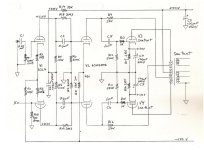
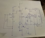
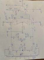
This one is a simple 2-stage Diff Amp, in this case driving a boot strapped, low mu triode.
The tails are taken to -150V, something easy to get from the regular HV CT PT most are using.
I've used variations of this on several amps, including a clone of Norman Crowhurst's Twin Coupled Amp, The Poor Man's McIntosh. 👍
The tails are taken to -150V, something easy to get from the regular HV CT PT most are using.
I've used variations of this on several amps, including a clone of Norman Crowhurst's Twin Coupled Amp, The Poor Man's McIntosh. 👍
Attachments
Thank you, that's another one I haven't seen. I think I'll see this design through though, I already have the entire PS section built.
Ok, brought it up tonight. Voltages are all in spec with what PSUD tells me will be there, for all 4 transformers (HT, bias, and 2 heater supplies). Nice.
Tomorrow I'll try to get the bias scheme finished, as you can see I got on it tonight. I'm debating whether I want to put a little resistance before the pots, but I think I'll stay with as much flexibility as possible. It's only an -80v supply, and I could come close to using that up studying how it behaves in different states. I do think I'm going to go for individual 20k after the pots, as opposed to the original shared 10k, so my range will be approx -40-80. And yes I'll get those safety bypasses on there as well 🙏
Getting closer a little at a time, thanks y'all,
Loren
Attachments
I have seen this happen WAY too often, 100% agree on this.Bias Pots that do not have a fixed resistor from the wiper to the most negative end of the Pot, are dangerous.
If the wiper makes a bad contact, the KT88s die.
Yeah that works too, either way the grids go full negative in a failure, thanks. I just got done changing the design a little, just ended up putting 4k in front of each pot, burn the last 10v of bias I'd never need and give the pots a little finer adjustment.
Time to wire heaters
What are some opinions on raising the heater voltage for the input and drivers? In the past I've just done the voltage divider off B+, to center of the 2 resistor artificial center tap. I was thinking raise it 70v, so that when the amps just starting to draw current I don't run into anything where it could possibly exceed the 6SL7's 90v peak positive heater to cathode. I think the 6sn7 will be less worried about it, but won't mind either
Thanks,
Loren
Just a quick update. Have the bias scheme all updated. Trying out mostly solder turret construction because I haven't before. I like it and could get used to it...bias supply was a little higher (raw) than I thought, which was good because now the LTP 6sn7 has a 33k tail instead of 28k. Looking like just a couple days left, finishing running out the B+ supplies, and installing the ground rails and remaining tube circuitry. Finally things are coming back to me and I don't have to search up and down every time I hit a wall, making the build process much more enjoyable.
Thanks again all,
Loren
Thanks again all,
Loren
Attachments
Oh and I had one question that I'm not easily finding the answer...are there any advantages/disadvantages to shared cathode resistors on the KT-88s? Each cathode will have a sense resistor, but then after those I thought maybe I'd tie their junction to whatever I decide to use for my mixed bias cathode resistors, which I was thinking around 100 ohms for each KT, or 50 if I shared them. Thanks all,
Loren
Loren
kb2wyl,
You said:
"are there any advantages/disadvantages to shared cathode resistors on the KT-88s?"
The answer is:
1. Are you using extremely well matched KT88 tubes? Good to go.
2. If not, then use Individual self bias resistors (and use individual bypass capacitors across each one).
3. Your output transformer laminations will Love you.
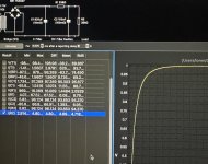
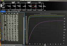
A look at the 3rd page from the bottom of the Heathkit W-5M owner manual will tell you why.
The amplifier was tested With global negative feedback in place.
The current balance was set precisely, then set at different levels of un-balance.
The graph of the low frequency harmonic distortion versus a little bit of un-balanced current showed the importance of balanced currents, even though global negative feedback was attempting to fix that problem.
0.2 Volts on the graph, is 3.3mA of un-balanced current; and 0.1 Volts on the graph is 1.7mA of un-balanced current.
Link to graph:
http://www.tubebooks.org/Books/Atwood/HeathkitW5M.pdf
Now, just imagine how high the bass distortion would be if there was no global negative feedback, but the current was slightly un-balanced.
Push pull without matched tubes (not only an emission match, other characteristics too), is like using 14 inch tires on the left side of the car, and using 15 inch tires on the right side of the car.
You said:
"are there any advantages/disadvantages to shared cathode resistors on the KT-88s?"
The answer is:
1. Are you using extremely well matched KT88 tubes? Good to go.
2. If not, then use Individual self bias resistors (and use individual bypass capacitors across each one).
3. Your output transformer laminations will Love you.
A look at the 3rd page from the bottom of the Heathkit W-5M owner manual will tell you why.
The amplifier was tested With global negative feedback in place.
The current balance was set precisely, then set at different levels of un-balance.
The graph of the low frequency harmonic distortion versus a little bit of un-balanced current showed the importance of balanced currents, even though global negative feedback was attempting to fix that problem.
0.2 Volts on the graph, is 3.3mA of un-balanced current; and 0.1 Volts on the graph is 1.7mA of un-balanced current.
Link to graph:
http://www.tubebooks.org/Books/Atwood/HeathkitW5M.pdf
Now, just imagine how high the bass distortion would be if there was no global negative feedback, but the current was slightly un-balanced.
Push pull without matched tubes (not only an emission match, other characteristics too), is like using 14 inch tires on the left side of the car, and using 15 inch tires on the right side of the car.
Last edited:
Thank you 6a3, and thank you for the graph link. I am using individual bias, regardless. That is the way the amp is constructed, and I rather like being able to quickly set operating points, and especially as you said, to balance the DC of the output stage. But since I am using a mixed bias scheme, with variable negative voltage to the grids but also a non-negligible resistance on the cathode. I've read positive things about this approach, using a cathode resistor in the ~20% of normal approach. And normally this amp at this voltage would be around 600ohm, so 100 was just a round number to start at.
I think because of this, I'll want to use individual resistors. Although there's more at play, from what I understand one of the benefit is the small amount of local negative feedback the resistor provides. That makes sense, but makes me think I wouldn't be able to tie the cathodes together and just use a 50ohm. Bias would still be adjustable, but I'm not sure I'd still get the mixed bias benefits like that?
Sorry I didn't explain more, I need to draw up and post another schematic, but the design is very close to the ones we did post earlier. There's another quick question, software just for drawing tube schematics? Thanks so much,
Loren
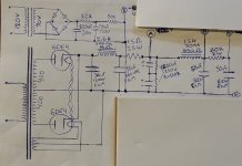
Please excuse the mess, just wanted it to keep current with what we're talking about. These are the actual values. I wasn't sure how to do the math for the capacitor on the LTP, but I'm thinking since I remember using a 1uf one time in the past, that I can get away with that. Hopefully, because I've got slim pickings on hand between .22 and 1uf right now.
Thanks,
Loren
Thanks,
Loren
Attachments
Last edited:
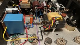
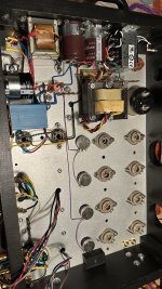
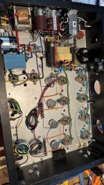
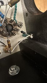
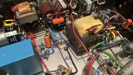
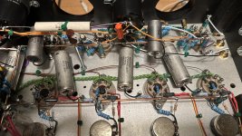
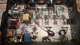
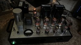
Well I got it built, powered up, biases balanced...Im getting a persistent buzz. All the voltages are right where my schematic says they should be. If I short the inputs, then I have to hold the test speaker right to my ear to hear it. I started trying feedback to the 6sl7 cathode to see what effect taming the gain would have, it didn't have much effect, though phase is correct. I think at the very least I need to change the input grid stoppers from 490 to a few k, but please check out the pics. Both channels are about the same level buzz, but especially with the right channel in picture the leads already are pretty darn short. But without feedback at least, just touching a test lead to the input jack (while trying to short it) caused a high pitched squeal oscillation.
Any suggestions aside from the grid stoppers? I feel like with as severe as it sounds, and both channels being equal when one has 6" more input wire, I'm missing something. Oh, when I power down and let the caps run it for a second, the buzz stays the same and just as harsh for those few seconds, no change in fact other then fading with the voltage.
I know it's close now, thanks all for your help with this one 🙏 oh, and first two pics are power supplies for b+ and bias, though the driver and input caps are grounded locally, and the last pic is what I mean about inputs being short already?
Loren
Attachments
Shoot no, it does I forgot to draw it in there a second time. It is a 470k grid leak on the 6sl7. That's what I get, I rushed a little when I realized it hadn't attached the first time. But aside from that I don't see any other mistakes vs actual circuit.
Yes! I got it. Changed a few things, referenced the input/driver heaters to ground through center tap of 250ohm 10-turn, instead of that center tap going to HV divider. Installed shielded input leads with only one end grounded. Tied end of ground bus to chassis at input (it was floating, with safety ground to chassis). Changed grid stops on 6SL7 to 4k7. I'm getting at least 35w before serious distortion begins, it blows away my stereomaster 340b, which is a nice sounding amp. I still need to figure out the feedback scheme and run some bandwidth tests on these OPTs, but it's fully operational and sounds great. Thanks you guys for helping get me back on track at the start, I surely do appreciate it.
Attachments
- Home
- Amplifiers
- Tubes / Valves
- 2 Octal splitter/driver combinations for KT88 amp