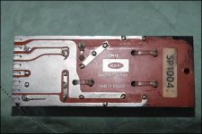
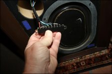
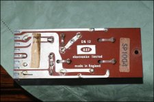
They look familiar. Prone to bad contacts over age. Since the PCB tracks look to be tinned maybe small holes can be drilled to fit 6.3 mm faston connectors. More reliable than soldering.
The connector will then be just a mechanical support. The easy way out (and worst choice) would be to solder wires from PCB to the connectors backside so the contacts are bridged.
The connector will then be just a mechanical support. The easy way out (and worst choice) would be to solder wires from PCB to the connectors backside so the contacts are bridged.
Last edited:
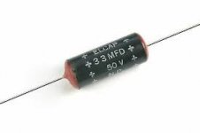
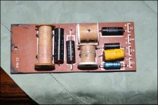
If your crossovers contain ELCAP bipolar electrolytic capacitors (see images), the capacitors are long overdue for replacement as they deteriorate badly with age.I have the Concerto since I was a teenager and I'm now 62...
Meanwhile , I can start my search for 2 other Dn12's (SP1004)...
Or maybe try to repair them first , once I know which parts are broken.
There's no need to go to the expense of replacing the crossovers in their entirety.
Attachments
Last edited:
Questions for Eric who wants (t)his problems solved:
1. What is the distance between the holes of the filter outputs? If you are lucky an 8 pin screw connector block can be soldered.
2. Did you already use the DMM to measure the continuity of the connector? Imagine the contacts to have lost pressure and that they don't make contact to the PCB tracks. Your DMM will then tell ∞
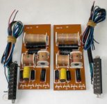
* the capacitors should all be replaced for optimal performance. They're very old bipolar electrolytic caps except for the blue one which is a polar capacitor and that one is chosen wrongfully anyway. Normally I replace at least the caps for the tweeter for film caps and add a few to have the same value but preferably a bit higher rated for like 100V. A careful DIYer chooses types that have good properties and fit physically as well so if that is a MKP 250V type 27.5 mm pitch so be it. Like a 4.7 µF in parallel with a 330 nF to have 5 µF and a 6.8 µF with a 220 nF in parallel for 7 µF. It may be a small difference but it does not cost much effort/money to obtain the exact value. For the very large values new bipolar electrolytic caps have to be found that are good quality.
1. What is the distance between the holes of the filter outputs? If you are lucky an 8 pin screw connector block can be soldered.
2. Did you already use the DMM to measure the continuity of the connector? Imagine the contacts to have lost pressure and that they don't make contact to the PCB tracks. Your DMM will then tell ∞
* the capacitors should all be replaced for optimal performance. They're very old bipolar electrolytic caps except for the blue one which is a polar capacitor and that one is chosen wrongfully anyway. Normally I replace at least the caps for the tweeter for film caps and add a few to have the same value but preferably a bit higher rated for like 100V. A careful DIYer chooses types that have good properties and fit physically as well so if that is a MKP 250V type 27.5 mm pitch so be it. Like a 4.7 µF in parallel with a 330 nF to have 5 µF and a 6.8 µF with a 220 nF in parallel for 7 µF. It may be a small difference but it does not cost much effort/money to obtain the exact value. For the very large values new bipolar electrolytic caps have to be found that are good quality.
Last edited:
I wouldn't be too fussy about the difference in values such as 5 and 4.7 uF in this vintage speaker crossover.
After all, the tolerance of the original ELCAPS was probably no better than 10%.
Yes, the blue electrolytics also require to be replaced.
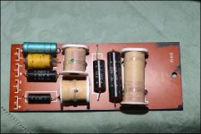
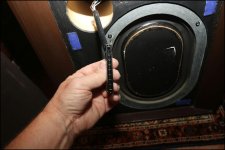
Eric, I can't quite see from your photo if the contacts in the end connector are corroded. How do they look to you?
EDIT: Jean-Paul could well be correct about the contacts making insufficient contact due to loss of springiness.
After all, the tolerance of the original ELCAPS was probably no better than 10%.
Yes, the blue electrolytics also require to be replaced.
Eric, I can't quite see from your photo if the contacts in the end connector are corroded. How do they look to you?
EDIT: Jean-Paul could well be correct about the contacts making insufficient contact due to loss of springiness.
Last edited:
He should measure (or learn how to measure) and not use eyes/assumptions. Sorry. Also the connector must not be used anymore as it is bad quality. Reinstalling it with the contacts bent to make contact again is not advisable. There is a very high chance it already failed.
Last edited:
Eric, I didn't say that the contacts could be damaged by IPA - please read my post more carefully.
My guess is that the contacts inside the edge connectors are corroded beyond rescue and that soldering the wires directly to the crossover board may solve your problem.
Please do not rush to the conclusion that you need to buy new crossover boards.
Oh Sorry Galu.
 My apologies .I try to understand everything you write, but 'technical English' is a bit harder for me to understand. Sometimes I have to use a translation program to understand what all of you write... sorry about that.
Personally , It think it would be quite a coincidence, that - just at the same time - both contacts of the edge connectors were irreparably corroded (beyond rescue).
The speakers were both playing. And only 5 minutes later , both of them don't play anymore. And all this happened, after the edge connector of CO1 was cleaned and the CO's were put in speaker1. I really can't see any corrosion, but perhaps that's difficult to see.
It's still a mystery to me.
But I certainly will wait to buy 2 new crossover boards. I have time...
There is absolutely no mystery when you measure the continuity. Waiting makes least sense of all. Also no need for new filters as it is likely the connector that failed. You will end up with having 4 filters and still no sound.
What language do you speak? Dutch or French? I will now go against forum rules for explanation.
Stelt u zich de kontakten in de connector met uw duim en wijsvinger voor en druk deze tegen elkaar. Schuif een printplaat tussen deze vingers en het klemt. Na vele jaren vermindert de druk en maken de vingers geen contact meer met de sporen op de printplaat. Eenvoudig te meten met de Ohm stand van de multimeter. Een meetpen op de printplaat en de andere op het kontakt waar de draad aan gesoldeerd is en als het goed is meet u dan 0 Ohm, bij een defect ziet u oneindig of MegaOhms. Dan is er simpelweg GEEN kontakt. Dit komt vaak voor bij deze connectoren als de "vingertjes" gecorrodeerd zijn en/of geen veerkracht meer hebben. Als het om het ingangskontakt gaat zult u inderdaad helemaal niks horen. Dat is dan geen mysterie maar simpele logica, er zit een denkbeeldige schakelaar in uw luidspreker en die staat op "uit".
Last edited:
... Please throw the contact spray away, it has no use in audio.
I do not agree and even think this is bad advice, it depends on the brand and composition of the product.

Therefor it is excellent advice as Murphy's Law says that the worst goo is sprayed on valuable electronics by laymen 😀
I think we understand eachother 🙂
I think we understand eachother 🙂
Last edited:
The connector on speaker one was already failing to make proper contact. Disturbing the connector on speaker two caused its contacts to fail also.It's still a mystery to me.
All the evidence points towards the connectors being faulty - not due to corrosion apparently - but due to a loss of springiness in the contact prongs.
As j-p says, you can confirm this simply by checking the continuity across the connectors using your multimeter.
If you need further help with that, just ask.
Last edited:
What springiness there is in those connectors is innate to the materials used, ie none designed in, I don't think they were ever meant to be disconnected, poor design.
Silveroxide is a conductor. Even the best conductors don’t sound well when interrupted 😉
Agreed, failure by design. Old Philips K12 chassis had the same construction and bridging the contacts was mandatory.
Agreed, failure by design. Old Philips K12 chassis had the same construction and bridging the contacts was mandatory.
My guess is that the contacts inside the edge connectors
They were bad even new. Bypass the connector. Solder the wire to the XO.
But the drivers have to be checked first. I have not seen your respnse on this.
dave
If you are actually going to replace the XOs i would consider a better XO. A few have been done. And with these, if you can bi-amp, a lower XO on the B139 hels suppress the 1k resonance.
dave
dave
- Home
- Loudspeakers
- Multi-Way
- 2 KEF Concerto's are dead now ...