BTW Rayma's circuit is essentially doing the same thing but using a traditional lpad to cut the lower frequencies bypassed at the higher frequencies. You could try adding the shunt resistor to the one that i have posted, it adds an additional tuning variable and should mean you can use a smaller series resistor (not sure why you had to go so high, but as I said, it all depends on your actual tweeters impedance curve).
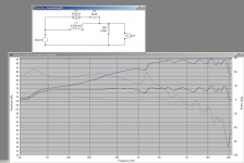
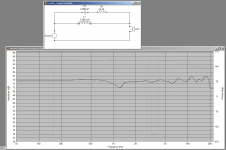
Below is the sim again with the shunt resistor, this is using the vifa impedance curve so is comparable to the very first one I posted. You can see it changes the values of the components a lot but gives you some additional flexibility. I've also added the original circuit I posted for comparison.
If you can get an impedance measurement of the tweeter you can use something like vituixcad to change values of components in real time to see their effects. Be careful with the shunt resistor though, too low a value will start to upset your amp like the big cap did.
REW is excellent for doing impedance measurements. provided you have a line out and line in on your soundcard, all you need is a simple cable with a resistor to do the impedance measurement. See Cables Note that it is recommened to use a resistor around 100 ohms (my original jig has an 8 ohm resistor which does work but I believe that the 100 ohm ref resistor gives more accurate results over a wider range.
Tony.
Attachments
Mmm, curves. Nice work 😉
msh, do you happen to have a photo of your headphones? They sound like a DIY delight.
msh, do you happen to have a photo of your headphones? They sound like a DIY delight.
Rather not use a shunt resistor, a series resistor simply works.BTW Rayma's circuit is essentially doing the same thing but using a traditional lpad to cut the lower frequencies bypassed at the higher frequencies. You could try adding the shunt resistor to the one that i have posted, it adds an additional tuning variable and should mean you can use a smaller series resistor (not sure why you had to go so high, but as I said, it all depends on your actual tweeters impedance curve).
Below is the sim again with the shunt resistor, this is using the vifa impedance curve so is comparable to the very first one I posted. You can see it changes the values of the components a lot but gives you some additional flexibility. I've also added the original circuit I posted for comparison.
If you can get an impedance measurement of the tweeter you can use something like vituixcad to change values of components in real time to see their effects. Be careful with the shunt resistor though, too low a value will start to upset your amp like the big cap did.
REW is excellent for doing impedance measurements. provided you have a line out and line in on your soundcard, all you need is a simple cable with a resistor to do the impedance measurement. See Cables Note that it is recommened to use a resistor around 100 ohms (my original jig has an 8 ohm resistor which does work but I believe that the 100 ohm ref resistor gives more accurate results over a wider range.
Tony.
Sadly i dont have a soundcard output to measure that, though at this point I have tried so many crossover combinations on these and im pretty settled on how the response should look like , my main "concern" as for now is settling on the right earpads, which have enormous effect on the sound.
AllenB, I will be honest and say there is nothing to see here atm, I will post a picture when i finish the project, one thing is for sure, they wont be pretty😀
Haha, it's partly about making us feel better about our own ugly contraptions 😀 (and admiring yours, of course 😉)
bumping this thread once more for a little help, I want to buy ~15MH inductor and I see there is some things i should be aware of when using a certain type of inductor when going into the low frequencies area (correct me if im wrong).
can you guys recommend a good inductor for my needs?
The budget is a maximum 50$ per inductor, but if there is a reason to go above that i would like to hear it out.
can you guys recommend a good inductor for my needs?
The budget is a maximum 50$ per inductor, but if there is a reason to go above that i would like to hear it out.
If your AMT has a simple, resistive looking impedance, and is used at lower power, then you shouldn't need a low resistance inductor.
A lot of people say to avoid cored inductors, but 15mH is big for an air cored!! Since this is for headphones, I would say that the main issue (that I've read about) with cored inductors you should never run into. That is that they become a problem if they saturate. Since the levels should be quite low for headphone output I doubt there is any risk of driving your inductors into saturation.
I've never used them, but the jantzen p-core inductors seem to fit the requirements Jantzen Audio 15mH 15 AWG P-Core Inductor Crossover Coil
This one with a laminated core also seems to fit the bill. ERSE Super Q 15mH 16 AWG 500W Inductor Crossover Coil
I guess size and weight are going to factor in as well, unless you have a separate crossover box.
Tony.
thanks guys
How is Erse overall? thinking of ordering the parts from their site, pretty cheap prices
How is Erse overall? thinking of ordering the parts from their site, pretty cheap prices
Not sure, I've only ever made my own coils, apart from a few very cheap no-name brand ones I bought for experimenting.
Sorry should have said I've never used the Erse inductors either 🙂 I don't think either would be an issue, for reasons already stated, but maybe someone with a different opinion will chime in 😉
Tony.
Sorry should have said I've never used the Erse inductors either 🙂 I don't think either would be an issue, for reasons already stated, but maybe someone with a different opinion will chime in 😉
Tony.
- Home
- Loudspeakers
- Multi-Way
- 1st-Order high value capacitor in parallel is possible?