OK I assume that it is correcting an over-correction in the first place... I'm still a bit confused 😀
Can you post the raw frequency response of the driver as well, and whatever circuit (including rayma's) you have as a crossover for the driver.
Tony.
Can you post the raw frequency response of the driver as well, and whatever circuit (including rayma's) you have as a crossover for the driver.
Tony.
This is not a tweeter, this has other drivers. Is there a woofer? What type is it?

Is there any crossover in it, please describe it?
I don't see the confusion
They're probably measuring at 1cm (or less) at extremely low levels. (again they are building headphones)
They're probably measuring at 1cm (or less) at extremely low levels. (again they are building headphones)
Oh, thanks that helps.
msh1999, when I first posted I didn't understand your problem. How is it now with rayma's circuit, is the bass OK?
msh1999, when I first posted I didn't understand your problem. How is it now with rayma's circuit, is the bass OK?
My confusion is around how do you go from the tweeters response to that (with just a single passive component)! linkwitz style transform? I realize that for headphones it is very low level, but I've never seen such extreme modification of a drivers natural response 🙂
Tony.
Tony.
I would think that most headphones operate below resonance.
If a headphone is very closely coupled to the ear, spl would be proportional to diaphragm displacement, not acceleration (as it is when radiating into free space).
So a tweeter used this way would probably be "flat" below resonance, and fall off at high frequencies.
Of course, in real life, the headphone won't be perfectly close-coupled to the ear, so frequency response will be somewhere between this idealised model and "normal" tweeter response.
Response curves for commercial headphones are generally all over the place - in comparison with loudspeakers.
I don't know why putting a C across the tweeter could possibly affect frequency response, other than by upsetting the amplifier in an unpredictable (and highly undesirable) way.
I`m still experimenting but here is a nice comparison so you guys will understand what I`m doing

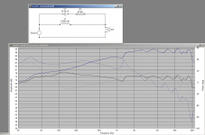
The red is using 1st order coil crossing, yes, it can be flatter but no matter what value I used after 2Khz~ there will be pretty extreme slope at that treble area and upward.
The black is after i applied the circuit rayma suggested.
green is the response without any crossover
as keithj01 said headphones measurements are all over the place, simply because its very tricky to measure them, on top of that i dont have a real reliable measuring rig so dont take my measurements as is,
especially when even the most accurate rigs out there cant measure treble reliably when it comes to headphones\earphones
Like in the first post? The amp has a small output impedance, eg a damping factor of 20 has a Zo of 0.4 ohms.I don't know why putting a C across the tweeter could possibly affect frequency response
The capacitor was huge. Its reactance is 0.4 ohms at 40Hz, and it would cut more with frequency until it catches up with the ESR of the cap and the response shelves.
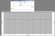
OK the very nearfield changes the response quite a lot, I couldn't see how the tweeter freq in the pdf earlier could possibly get to the sort of response that you were showing. Using a trace of your "standard" response I put it in speakerworkshop (since I don't have an impedance curve for the tweeter I just used a random vifa tweeter curve I had) and below is the result. If you do something like this I think you will be on the right track 🙂 note 8 - 10 uf for the cap is a bit better, but since I don't have proper impedance curves the values could be wildly different from what I have posted..
Tony.
Tony.
Attachments
Last edited:
headphones measurements are all over the place, simply because its very tricky to measure them
Now I see what you're doing, it needs some eq in the drooping treble above 4kHz, though.
Do you measure with a sealed cup on a baffle? How does it sound? Pretty big elements for phones.
Like in the first post? The amp has a small output impedance, eg a damping factor of 20 has a Zo of 0.4 ohms.
The capacitor was huge. Its reactance is 0.4 ohms at 40Hz, and it would cut more with frequency until it catches up with the ESR of the cap and the response shelves.
Just re-read the first post - it's 10,000 uF, and I read it initially as 10uF!
Ouch!
Yeah it's no wonder the amp didn't like it! 🙂 It's effectively a dead short over a very large frequency range...
Tony.
Tony.
interesting! I will try this out and if it wont work i will bother with more details to try and make the headphones achieve such a nice response.OK the very nearfield changes the response quite a lot, I couldn't see how the tweeter freq in the pdf earlier could possibly get to the sort of response that you were showing. Using a trace of your "standard" response I put it in speakerworkshop (since I don't have an impedance curve for the tweeter I just used a random vifa tweeter curve I had) and below is the result. If you do something like this I think you will be on the right track 🙂 note 8 - 10 uf for the cap is a bit better, but since I don't have proper impedance curves the values could be wildly different from what I have posted..
Tony.
Will update regarding the results in a few hours I hope
rayma
i rather experiment as much as i can before turning to EQ in the treble area.
the headphones are sealed type, also with earpads when measuring,
The driver is big for headphones, i use a slightly smaller earpads than the driver itself at the moment in order to focus the waveform into the ear canal because of that, but at this point everything is still bound to change.
as for the sound ,they sound really nice, wouldn't mind to stop at this exact point and enjoy these.
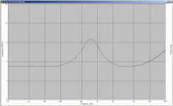
The results will vary depending on the impedance of the tweeter. I used the impedance curve of a vifa d25ag-35-06 it has a fairly low resonance peak at somwhere between 500 and 1000Hz which is actually helping to give that very flat response. I tried with a dead flat 4 ohms impedance and the result is not as good.
The topology should work though. Just the values and the flatness may vary. Do you have an impedance measurement of the driver?
edit: the attached was the impedance curve used which gives the really flat response. Some of the AMT tweeters I looked at from dayton had essentially resistive impedance, completely flat at 4 ohms. If your tweeter is like that then the result may be more like the second attachment which was simmed with a flat 4 ohms impedance.
I did think perhaps it would be possible to insert a tweeter equivalent circuit into the tweeters earth leg to simulate the vifa's impedance peak, not something I've ever tried before, would be interesting to see if it would work....
Might open up some interesting posibilities for response tayloring! I've never seen it done before (possibly for good reason!!). BUT have an experiment with the topology I showed and lets see what results you get.
Basically it is a band stop filter. The coil is rolling off the lows but the cap in parallel with the resistor in series with it, is bypassing the coil at the higher frequencies. The resistor provides the attenuation to bring the highs down to the level that the coil is rolling the low end down to. It works much better than I expected it to... The resistor in series with the cap also stops the coil and cap from forming a resonant circuit which would normally result in a deep notch.
Tony.
Attachments
Last edited:
You still have these? I think they were one of the best tweeters Jaycar offered.vifa d25ag-35-06
Haha I just posted in another thread (in response to you Allen) that I couldn't stand them 😀 I had traced the impedance curve at some point when I was helping someone to try and improve a crossover and they didnt have any real measurements.
What I don't know though is whether the problem was the implementation, I heard them in some of the kit speakers that Jaycar had in store. Different ones over the years, but none of them I actually liked. They had a tinny/tizzy sound to them that really bugged me.
Tony.
What I don't know though is whether the problem was the implementation, I heard them in some of the kit speakers that Jaycar had in store. Different ones over the years, but none of them I actually liked. They had a tinny/tizzy sound to them that really bugged me.
Tony.
They drove me crazy. I threw crossover after crossover at them trying to get it right, but after I stopped using them I wanted them back (after I'd damaged the domes and jaycar had stopped selling them of course)
Last edited:
I would kiss you if were here!The results will vary depending on the impedance of the tweeter. I used the impedance curve of a vifa d25ag-35-06 it has a fairly low resonance peak at somwhere between 500 and 1000Hz which is actually helping to give that very flat response. I tried with a dead flat 4 ohms impedance and the result is not as good.
The topology should work though. Just the values and the flatness may vary. Do you have an impedance measurement of the driver?
edit: the attached was the impedance curve used which gives the really flat response. Some of the AMT tweeters I looked at from dayton had essentially resistive impedance, completely flat at 4 ohms. If your tweeter is like that then the result may be more like the second attachment which was simmed with a flat 4 ohms impedance.
I did think perhaps it would be possible to insert a tweeter equivalent circuit into the tweeters earth leg to simulate the vifa's impedance peak, not something I've ever tried before, would be interesting to see if it would work....
Might open up some interesting posibilities for response tayloring! I've never seen it done before (possibly for good reason!!). BUT have an experiment with the topology I showed and lets see what results you get.
Basically it is a band stop filter. The coil is rolling off the lows but the cap in parallel with the resistor in series with it, is bypassing the coil at the higher frequencies. The resistor provides the attenuation to bring the highs down to the level that the coil is rolling the low end down to. It works much better than I expected it to... The resistor in series with the cap also stops the coil and cap from forming a resonant circuit which would normally result in a deep notch.
Tony.
works perfectly ,I must say that the tuning i got from the circuit rayma gave me still weirdly got the upper hand but i still have to do some listening.
the coil is about the same as value as your first post suggested
The capacitor is slightly weird case, it doesn't make differences from about 8UF to 350UF value in the response, but at 3.3UF~ there is a sudden change
the resistor needed to be at a much higher value (around 100-200 at the graph below)
just to show the flexibly it gave me, the changes at the treble response are being done only by changing the resistor`s value.


- Home
- Loudspeakers
- Multi-Way
- 1st-Order high value capacitor in parallel is possible?