ripple @ the output should be well under 5mV so 3.5V ripple on the rails will need an awful good PSRR
even 1mV @ the output of those bass drivers will cause about 75dB of noise @ 1M
and 3.5V is about 2% of the rail
even 1mV @ the output of those bass drivers will cause about 75dB of noise @ 1M
and 3.5V is about 2% of the rail
There is something wrong here, because 3.47V is near 2% ripple if you consider, for example 180V per rail. 2% is a reasonable ripple under full load, I think, but, remember, your load is not constant and you might consider your mains capacity too.
It seems to me you can use these values and change it at your tests if you wish. someone above says something about making one or two units first to perform a fine tuning of your design. I think it is a wise advice.
Regards
It seems to me you can use these values and change it at your tests if you wish. someone above says something about making one or two units first to perform a fine tuning of your design. I think it is a wise advice.
Regards
Won't there be a huge inrush of current when you turn on the amp? Wont the caps draw a monsterous amount of current without limiting their initial turn on charging because of being directly connected to the mains? Also, what about the fact that a standard U.S. outlet is only capable of supplying 120V at 15 amps? Is that enough to quench your creations thirst? Are you going to have multiple circuits run to where the amp will be living?
What is this frakenstein project going to be powering, a small town? And do you have schematics of the amp you want to build 🙂 If you do I want to see them cause I like overkill😀
What is this frakenstein project going to be powering, a small town? And do you have schematics of the amp you want to build 🙂 If you do I want to see them cause I like overkill😀
The amp will plug into a standard American range outlet, which can supply 240VCT, 50A. Yes, there will be a huge inrush of current at startup, and it wouldn't surprise me if it makes the neighbors' lights dim for a second or so, but I will have 600V, 150A discrete diodes in the power supply, so it ought to handle it.
It will power 8 Audiobahn ALUM12X subwoofers as part of a tri-amped system easily capable of 140+dB @1M.
As for the schematics, I'm still designing it, but the front end will look a lot like the Leach Superamp with 20 MOSFETs instead of 8 BJTs, and the rest will look a lot like one of Randy Sloan's high performance MOSFET amps. I am hoping for a THD of less than 0.1%, and the amp will be capable of driving almost any speaker system you can throw at it. Not to brag, but hopefully, I will end up with one of the best super high-performance, painfully powerful high end class AB,B MOSFET amps that can possibly be built by an ordinary audiophile. 😀
Huh, I have two in my house, but I don't see how I can give you one.🙂 Almost all American households have at least one, we plug our ovens and arc welders into them. We use very similar 30A outlets for clothes dryers, surely you must have one too. What do you do when you need lots of power?
we have 240V 10A outlets..... not CVT ... for higher power he have 15A outlets... speacial 20A distribution plugs and 3-phase when higher voltage is needed. higer current is generally only available for industrial installations.
Interesting. Anyway, on a different subject, I am finding it a little confusing trying to modify the Randy Sloan type topology to have series-arranged output devices like the Leach Superamp. This is because the Leach design has a predriver stage (Q14 and Q15, here's a link http://users.ece.gatech.edu/~mleach/superamp/ ) that does not exist in Sloan's design. This stage seems rather critical in the double-barelled OPS design of the Superamp, but I'm rather inexperienced with such things.
Kilowatt, convert it to Class G
It seems like the Leech Super Amp is practically Class G. It seems like you could add a lower level power supply at 2/3 the level of the highest level. Then you connect diodes to the lower transistors to allow them to withstand reverse bias as the upper ones take over. The trade-off as I understand is some extra distortion as the storage charge on the lower transistors' bases prevents them from switching seamlessly. But the Hitachi amp that was using the technique did not spec with very poor distortion figures. But after the modifications, I doubt the amp could be considered low TIM any more.
It seems like the Leech Super Amp is practically Class G. It seems like you could add a lower level power supply at 2/3 the level of the highest level. Then you connect diodes to the lower transistors to allow them to withstand reverse bias as the upper ones take over. The trade-off as I understand is some extra distortion as the storage charge on the lower transistors' bases prevents them from switching seamlessly. But the Hitachi amp that was using the technique did not spec with very poor distortion figures. But after the modifications, I doubt the amp could be considered low TIM any more.
KiloWatt, those audiobahn alum 12's don't need "that" much power to play very loud. I know this because I have 3 of them in a linkwitz transform setup, and as we all know linkwitz transforms need a lot of power. I was using a crown ce1000 to power my three wich was a 4 ohm load (12 ohm each, then all in parrallel). It was a good matchup. I could exceed xmax at 20hz. I still use the same 3 audiobahn alum 12's now, but I use a CE2000 i picked up dirt cheap. The alum 12's are a very effeicent sub. I have been able to hit over 130db in my house at around 50 hz. These subs get way loud. I am also no where near maxing out the amp either. Either way your setup is going to be sweet.
Don't bother Jeremy. Kilowatt has already made up his mind. Even though his subs will reach excursion limits long before they get to 7200Watts, never mind that running an amp of this size directly off a 240V line is an increadibly dangerously bad idea, even after person after person has recommended trying somthing a little less collosal for a first DIY amp project. He is unwilling to listen.
I'm just waiting for the post where he tells us about the $500 in transistors that just went up in smoke, or how his house just burnt down and the insurance company won't cover a thing, or how he's now picking up bits of speaker from his room. God hoping that he doesn't end up killing himself.
I'm just waiting for the post where he tells us about the $500 in transistors that just went up in smoke, or how his house just burnt down and the insurance company won't cover a thing, or how he's now picking up bits of speaker from his room. God hoping that he doesn't end up killing himself.
I don't think the SuperAmp could be considered class G in any way, because it only utilizes 1 set of supply rails and always draws from them. It just has the outputs and drivers in series so they don't see as much voltage. I'm just wondering where I should put the emitters of Q24 and Q25 to use this series OPS setup with a topology like the one at http://www.aussieamplifiers.com/sym-sch.htm, or other MOSFET designs, instead of the Leach topology, because those MOSFET amps don't have a predriver stage, which is what Q24,25 are in series with.
AudioFreak,
About the ripple at full load, I think you might consider the class of the amp and its current draw characteristic to define a good or bad ripple characteristic for the power supply. Based on Kilowatt informations about the circuit, if I remember well, .005V will be near 100dB below the signal (considering peak to peak excursion). At quiescent levels, Icc will be low and the Vripple will follow it (70mV for Icc=1A, for example, using the same equation).
I really don´t remember for now, but in my prototype (made near 20 years ago 😀 ), I used 10000uF per rail and I had no problems with hum or noise at the output, I remember THD+Noise was below .1% in any case.
regards
Kelly, I just lost $500 worth of OP transistors, and they took $1400 worth of subs with them, and my house burned down too and the insurance won't cover it. None of that's actually true, of course, since I won't even be finished designing this thing by the time I have my Leach amps done, but at least you heard the post you've been waiting for. Now would you please not try to make this thread go where my other one on this project did. This isn't going to be my first project, it's just that I've already started thinking about how I'm going to do it, and I know some people have said not to do it, but many have actually helped me on it too, rather than just telling me to drop it and go into quilting or something. You seem to think that having 300V wiring in a closed, grounded box with isolated hookups is more dangerous than motorcycle stunt driving. And I'll probably get more Audiobahns so they won't xmax so easily, but after the amp's done. Anyway, what do you expect me to do? Just forget about the whole thing? Let me tell you something... NO! Would you? Also, I believe Jeremy rather likes this idea, with quotes like "If you do I want to see them cause I like overkill😀 " and "Either way your setup is going to be sweet."
I suggest that we all forget about Kelly's post because it seems to aimed at breaking down our discussion.
Anyway, it sounds like I should test the amps before I decide just how much capacitace I'll end up having to have.
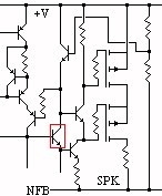
About my series OPS, shown below is a small section of what seems a reasonable topology for my amp. I am assuming that most people on the forum recognise where in the amplifier circuit this is, and can tell where all the loose ends lead. I would like to eliminate the stage highlighted in red, as it is normally not found in MOSFET amps, but I can't seem to find a way to because I don't know where to put the transistor that goes in series with it, the one with the voltage divider at it's base. In fact, I'm not even sure if this would be the proper way to put MOSFETs in series. Maybe there's something better. Any ideas?
I suggest that we all forget about Kelly's post because it seems to aimed at breaking down our discussion.
Anyway, it sounds like I should test the amps before I decide just how much capacitace I'll end up having to have.
About my series OPS, shown below is a small section of what seems a reasonable topology for my amp. I am assuming that most people on the forum recognise where in the amplifier circuit this is, and can tell where all the loose ends lead. I would like to eliminate the stage highlighted in red, as it is normally not found in MOSFET amps, but I can't seem to find a way to because I don't know where to put the transistor that goes in series with it, the one with the voltage divider at it's base. In fact, I'm not even sure if this would be the proper way to put MOSFETs in series. Maybe there's something better. Any ideas?
Attachments
blmn said:AudioFreak,
About the ripple at full load, I think you might consider the class of the amp and its current draw characteristic to define a good or bad ripple characteristic for the power supply. Based on Kilowatt informations about the circuit, if I remember well, .005V will be near 100dB below the signal (considering peak to peak excursion). At quiescent levels, Icc will be low and the Vripple will follow it (70mV for Icc=1A, for example, using the same equation).
I really don´t remember for now, but in my prototype (made near 20 years ago 😀 ), I used 10000uF per rail and I had no problems with hum or noise at the output, I remember THD+Noise was below .1% in any case.
regards
Yep i didnt think about that @ the time 🙂
What good audio design and analysis software can I get for a reasonable price? I've heard about Electronics Workbench, but it's hundreds of dollars, the pro version is thousands of dollars. It would be nice if the design software was less expensive than the amp I'm going to design with it.
Kilowatt,
Honestly I don't think there are any cheaper packages out there that are worth your time, or that have enough pin or part capacity for what you are doing. At times, I have been able to break larger circuits into smaller chunks (i.e. individual stages) and simulate with Pspice... but this doesn't always give you the whole picture..
My suggestion is to find someone who has a copy of what you need =)... good luck though! Be prepared to spend hundreds of dollars otherwise.
Kilowatt said:What good audio design and analysis software can I get for a reasonable price? I've heard about Electronics Workbench, but it's hundreds of dollars, the pro version is thousands of dollars. It would be nice if the design software was less expensive than the amp I'm going to design with it.
Randy
It is clear what you are suggesting, but it is not in keeping with the spirit of this forum to advocate a breach of copyright.
Geoff
It is clear what you are suggesting, but it is not in keeping with the spirit of this forum to advocate a breach of copyright.
Geoff
I wasn't implying that copyrights need to be broken... is it illegal to use someone's computer?
Geoff said:Randy
It is clear what you are suggesting, but it is not in keeping with the spirit of this forum to advocate a breach of copyright.
Geoff
I'm not suggesting you give up on the project, but that you take a realistic approach towards achieving it. Its not a trivial or cheap project you are attempting here, and as may people have noted there are many, many, many factors that you will have to take into account. Many things that you can pretty much safely ignore when building a small amp, become very significant when building a large one.
Like I said before its very much like wood working, if you're just building a bookshelf out of plywood then you really don't have to worry about things like warping or shrinkage. However you go and build a solid oak table, then suddenly there are a whole buch of other factors you need to consider. Its also like building models, you don't have to worry about much with a snap-tite model, but you try and build a vacuform or resin model and suddenly it gets a lot more complicated.
Try building a few smaller simpler amps first, then play around with modding them. The cost of doing this is going to be a whole lot less than loosing 7200 Watts worth of parts.
300V inside a sealed enclosure isn't the big problem, as long as the inputs are opto-isolated and the speakers and amplifiers are in the same enclosure then its not as big a safety issue under normal operating conditions. However, note I said under normal operating conditions, since this is a prototype design and from what you said essentially your first attempt, normal operating conditions cannot be assumed. Design flaws, component drift, SOA and injected noise will all become serious factors. With a 50W amp, $20 bucks in output transistors and 40V a failure isn't going to be catastrophic. However you're talking several hundred dollars in outputs and a full 240V 50 Amp line, if this thing blows its going to go out in a very big way.
Belive it or not but I'm trying to help you, help you save alot of money and frustration. You know the number one reason people abandon hobbies is because they take on a very abitous project for thier first attempt, when it invariably fails they get discouraged and abandon it as a whole.
Also expect to spend several hundred dollars in equipment to build and debug this amp, you are going to need (or borrow), multimeters, modelling software, an oscilloscope, a signal generator would be nice too, so would a variable transformer that way you can power the thing up slowly (but a 240V, 50Amp variable transformer is probably going cost an arm an a leg). Ebay is a good source of cheap used test equipment. Still this project is going to cost quite a bit when all is said and done
However it is your life to do with as you please, but you are asking for help and opinions. I'm just giving you my advice, personally I would start by modelling the enclosures you are planning on using, this way you can determine how much power you are really going to need (you'll probably be surprised at how little it is), then instead of building one collosal amplifier (or bridging together a whole bunch of amps), you build a seperate amp for each driver. This way a single failure isn't going to take everything down and you have additional flexibility. Once you're confident with your ability, then you can try bridging them together to try and increase output.
This will be my last post on the matter and I wish you luck
- Status
- Not open for further replies.
- Home
- Amplifiers
- Solid State
- 1kW MOSFET amplifier