This is my first attempt at fault finding using SPICE, I have been a SPICE user for 3 days. I'd like to credit mjona for getting me started, his tireless efforts (he was later joined by others) in AndriyOL's 'Reasons Of Oscillations........' thread - uploading and editing asc files, finally gave me the push I needed to get off the SPICE sidelines 🙂
I copied the circuit from a service manual because the equipment is not overly 'serviceman friendly' - access covers being somewhat out of vogue these days, and it looked like a great opportunity to gain some 'hands on' SPICE experience.
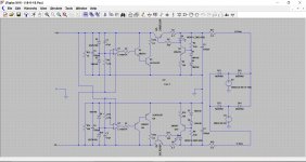
A few notes regarding the PSU: Looking at the top + half of the mirrored layout, everything to the right of Q5 looks to me like the makings of a constant current supply. Everything to the left is dedicated to shunting this current to ground via Q3, in accordance with the reference set by D5 and implemented by U1.
I have added R13 and R14 to simulate unequal loads, as is so often the case in the real world. Also, the source supply +28 0 -29 is asymmetrical because of unequal loading of the raw incoming and unregulated DC supply (the incoming V+ feed also supplies another separate circuit).
The SPICE circuit wouldn't work initially because the LED I got from the library must have been a fake 🙂 At any rate, it had a volt drop like a normal 4148 which prevented the constant current part of the circuit from working. After substituting the 'dud' part with a proper LED, it all worked fine.
The 0.1 ohm resistors were added by me so I could see how much current was being shunted by Q3 & Q8.
What an incredible tool! Highly recommended, no matter what your electronics skills level. For what it's worth, I'm over 50 and not the fastest learner. If anyone has any suggestions or comments regarding my implementation of the circuit, please feel free to share.
With regard to the OP37 op amp. The original circuit used a dual 4559 device. I couldn't find one in the library (I confess I didn't look too hard) so ended up 'winging it' with two singles, it just made the supply lines a bit messy, having to run to 2 devices. Not sure if I did the voltage sources correctly? I needed a split rail supply. And I didn't pay too much attention to the transistor ratings and power dissipation, there will certainly be devices better suited to the application. However, in simulation land, the ones selected are doing a sterling job!
I copied the circuit from a service manual because the equipment is not overly 'serviceman friendly' - access covers being somewhat out of vogue these days, and it looked like a great opportunity to gain some 'hands on' SPICE experience.
A few notes regarding the PSU: Looking at the top + half of the mirrored layout, everything to the right of Q5 looks to me like the makings of a constant current supply. Everything to the left is dedicated to shunting this current to ground via Q3, in accordance with the reference set by D5 and implemented by U1.
I have added R13 and R14 to simulate unequal loads, as is so often the case in the real world. Also, the source supply +28 0 -29 is asymmetrical because of unequal loading of the raw incoming and unregulated DC supply (the incoming V+ feed also supplies another separate circuit).
The SPICE circuit wouldn't work initially because the LED I got from the library must have been a fake 🙂 At any rate, it had a volt drop like a normal 4148 which prevented the constant current part of the circuit from working. After substituting the 'dud' part with a proper LED, it all worked fine.
The 0.1 ohm resistors were added by me so I could see how much current was being shunted by Q3 & Q8.
What an incredible tool! Highly recommended, no matter what your electronics skills level. For what it's worth, I'm over 50 and not the fastest learner. If anyone has any suggestions or comments regarding my implementation of the circuit, please feel free to share.
With regard to the OP37 op amp. The original circuit used a dual 4559 device. I couldn't find one in the library (I confess I didn't look too hard) so ended up 'winging it' with two singles, it just made the supply lines a bit messy, having to run to 2 devices. Not sure if I did the voltage sources correctly? I needed a split rail supply. And I didn't pay too much attention to the transistor ratings and power dissipation, there will certainly be devices better suited to the application. However, in simulation land, the ones selected are doing a sterling job!
Attachments
That's a really good first attempt 🙂
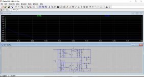
The DC conditions all seem good and so the next step is to test it dynamically and look at the ripple content of the output.
The opamp used seemed to have a problem in that it caused the simulation to run slowly once the output voltages reached their nominal values. There could be a number of reasons for that, one being that some low level instability was occuring and slowing the sim down. I swapped the opamp to the basic LT1001 (sort of 741 ish) and that fixed the issue. The LT1056 is another standard part to try (FET opamp like a TLO71).
Its looking good... you can have a play 😀
Attachments
How do you turn the base of the power transistors on? There is no current source.
Good start though.
Good start though.
Which transistors are you looking at Jon ? Is it Q5 and Q7, the series pass elements. Q5 is PNP and turned on by pulling the base toward ground.
Correct. It is because the schematic is drawn the wrong way around. Right to left instead of the norm.
My mistake!
My mistake!
Last edited:
That's a really good first attempt 🙂
The DC conditions all seem good and so the next step is to test it dynamically and look at the ripple content of the output.
The opamp used seemed to have a problem in that it caused the simulation to run slowly once the output voltages reached there nominal values. There could be a number of reasons for that, one being that some low level instability was occuring and slowing the sim down. I swapped the opamp to the basic LT1001 (sort of 741 ish) and that fixed the issue. The LT1056 is another standard part to try (FET opamp like a TLO71).
Its looking good... you can have a play 😀
Thanks Mooly, you have to take some of the credit too. Mjona suggested I look at your tutorial and I did just that. I'm still on page 2 though, with about 133 to go 🙂 I'd seen your tag line before of course, but I always assumed you did that privately or as your occupation.
Thanks also for the modified asc (I will play some more tonight), and especially the tips on op-amp selection. I had gotten no further than the .op command and wouldn't have had the experience to know if anything was amiss.
It seems it is no longer possible to get updated libraries from LT. The vesion I downloaded over the weekend V4.231 is the same version I downloaded 440 days ago but never used. The library files sizes appear to be identical. Is that indeed the case?
Correct. It is because the schematic is drawn the wrong way around. Right to left instead of the norm.
My mistake!
Hi Jon,
Thanks for responding. I see Mooly has already explained the circuit to you. I must say, when I first looked at the diagram I was rather surprised at the method of regulation myself. What made it worse was it's a commercial design and it wasn't regulating very well at all. So I kinda wondered if it had been designed properly in the first place, hence the desire to simulate it.
With regard to layout: Almost every service manual I've ever seen has the transformer on the right of the page and they work left from there. Offhand, I can't think of a single manual I've used recently that was different. I work mostly on consumer SS audio gear, AVRs etc.. Nevertheless, if there is a SPICE layout protocol, I will of course try to abide by it.
Thanks Mooly, you have to take some of the credit too................
Thanks for the kind words 🙂
LTSpice IV is now classed as a legacy program and is out of support.
If you are running anything newer than Windows 8.1 then LTSpice XVII is latest version to go for.
Lineartech is now part of Analog Devices.
LTspice | Design Center | Analog Devices
Attachments

Hi Mooly
Think I've found something. I don't think the speed at which the simulation runs has anything to do with the choice of op-amp.
Remember right at the beginning of your tutorial you recommend turning off auto-saving of various files? I suspect it's to do with that. (I did as you advised because I'd already noticed how those files can multiply)
When I ran your modified asc file, the simulation was also painfully slow. So slow, the scope screen has time to refresh with a completely different scale! But if you run it again (without exiting the file or closing LT), then it runs faster.
I cross-checked this by copy pasting your modified psu (thanks for that 🙂 ) into my original file with the OP37. Same story. Runs slow the first time but afterwards it's fine.
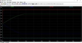
There is a noticeable difference in op-amp performance though, see attached screen capture and compare it with the one you took. Your op-amp is settled in under 0.3s, the OP37 takes the best part of 0.9s, that is, if I'm interpreting the data correctly.
That's not to say it's the op-amps fault though. It might just be that the peripheral values chosen suit the one device better than the other.
Oh man is this addictive 🙂 I know there exists the term 'computer widow'. I wonder if there are 'SPICE widows' out there; women living with men who have become complete strangers because they never see them any more (the SPICE addicts). 🙂
Think I've found something. I don't think the speed at which the simulation runs has anything to do with the choice of op-amp.
Remember right at the beginning of your tutorial you recommend turning off auto-saving of various files? I suspect it's to do with that. (I did as you advised because I'd already noticed how those files can multiply)
When I ran your modified asc file, the simulation was also painfully slow. So slow, the scope screen has time to refresh with a completely different scale! But if you run it again (without exiting the file or closing LT), then it runs faster.
I cross-checked this by copy pasting your modified psu (thanks for that 🙂 ) into my original file with the OP37. Same story. Runs slow the first time but afterwards it's fine.
There is a noticeable difference in op-amp performance though, see attached screen capture and compare it with the one you took. Your op-amp is settled in under 0.3s, the OP37 takes the best part of 0.9s, that is, if I'm interpreting the data correctly.
That's not to say it's the op-amps fault though. It might just be that the peripheral values chosen suit the one device better than the other.
Oh man is this addictive 🙂 I know there exists the term 'computer widow'. I wonder if there are 'SPICE widows' out there; women living with men who have become complete strangers because they never see them any more (the SPICE addicts). 🙂
Attachments

I was just looking at this as well 🙂
I've found a few things that might be going on...
The sim I posted runs in around 4 or 5 seconds I guess. I've got a different variation on the screen just now. I'll tell you more in a minute.
I've found a few things that might be going on...
The sim I posted runs in around 4 or 5 seconds I guess. I've got a different variation on the screen just now. I'll tell you more in a minute.
Here is what I am thinking... and try this.
With the LT1001 opamp fitted reduce C5 and C6 to 10uF. It becomes unstable and the rails are full of HF oscillation.
I suspect the problem is that the 18 volt zener can only conduct when 18 volts is reached and yet that is also the supply voltage required. The opamp only runs on +18 volts.
This is what I have done.
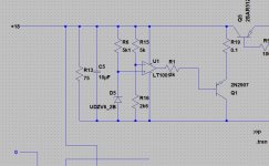
1/ Reconfigure the zener using a 6.2 volt device. It is now ground referenced.
2/ Rehash the opamp to give gain. You now have control over the output voltage by altering the resistor values (you could make one a preset).
3/ The opamp negative supply is now ground referenced.It doesn;t need the -18 volt supply. The same would apply to the lower opamp. The positive supply pin would go to ground and you retain the -18 volt.
4/ Many opamps can't swing the output to ground. They can only reach a within a volt or so and so I have used a PNP shunt transistor and flipped the opamp inputs to suit. A FET could be a possibility here.
I've just done the positive rail.
With the LT1001 opamp fitted reduce C5 and C6 to 10uF. It becomes unstable and the rails are full of HF oscillation.
I suspect the problem is that the 18 volt zener can only conduct when 18 volts is reached and yet that is also the supply voltage required. The opamp only runs on +18 volts.
This is what I have done.
1/ Reconfigure the zener using a 6.2 volt device. It is now ground referenced.
2/ Rehash the opamp to give gain. You now have control over the output voltage by altering the resistor values (you could make one a preset).
3/ The opamp negative supply is now ground referenced.It doesn;t need the -18 volt supply. The same would apply to the lower opamp. The positive supply pin would go to ground and you retain the -18 volt.
4/ Many opamps can't swing the output to ground. They can only reach a within a volt or so and so I have used a PNP shunt transistor and flipped the opamp inputs to suit. A FET could be a possibility here.
I've just done the positive rail.
Attachments
2/ Rehash the opamp to give gain. You now have control over the output voltage by altering the resistor values (you could make one a preset).
Poor choice of words. Its configured more as a comparator but the ratio of the two resistors sets the point at which the opamp will change states.
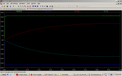
This shows how quickly the pos rail can now rise without the 3300uF cap.
Attachments
Last edited:
I'm just running my original modified file and it takes 12 seconds to run. A re-run without deleting or altering anything still takes 12 seconds but this is on LTXVII and not LTIV
Back later... have fun 🙂
Back later... have fun 🙂
Here is what I am thinking... and try this.
With the LT1001 opamp fitted reduce C5 and C6 to 10uF. It becomes unstable and the rails are full of HF oscillation.
I suspect the problem is that the 18 volt zener can only conduct when 18 volts is reached and yet that is also the supply voltage required. The opamp only runs on +18 volts.
This is what I have done.
1/ Reconfigure the zener using a 6.2 volt device. It is now ground referenced.
2/ Rehash the opamp to give gain. You now have control over the output voltage by altering the resistor values (you could make one a preset).
3/ The opamp negative supply is now ground referenced.It doesn;t need the -18 volt supply. The same would apply to the lower opamp. The positive supply pin would go to ground and you retain the -18 volt.
4/ Many opamps can't swing the output to ground. They can only reach a within a volt or so and so I have used a PNP shunt transistor and flipped the opamp inputs to suit. A FET could be a possibility here.
I've just done the positive rail.
Very nice Mooly, I can't get it to work though. It simulates fine in .tran 1 mode but when I make the .op command active, no voltage anywhere. There are no warnings when the netlist is compiled. I can't see any changes to the settings either. It is interesting to compare the bottom and top rails though, the + rail comes up in a blinding flash. 🙂 Are there any known compatibility issues between XVIII and IV?
Try this one 😉 This runs instantly in LTXVII
I'll leave it to you to experiment with better shunt transistors (darlington or FET !). I think I would also take those 0.1 ohm monitoring resistors out of the circuit as they will hamper the shunt regulator... I have done.
You can monitor the current by carefully placing the cursor over the emitter and getting the cursor symbol to change. Then left click. You'll get the hang of that with practice.
Attachments
Posted together 🙂
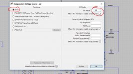
The .op command wont work for this simulation because the voltage sources are AC. If you want to run a pure DC simulation then I would suggest saving the circuit again under a new name. Now open and change each voltage source to 'none' and then add the DC voltage required which is +28 for the top source and -28 for the lower.
You can leave the bridge in place.
Its quicker having two sims than keep changing things I find.
More tomorrow 😉
Attachments
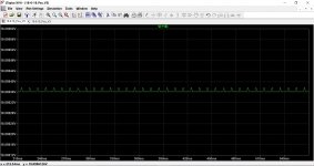
One last thing for today. If you place your cursor just above the actual trace of the rail, and then left click and hold the button, you can 'drag' a rectangle around the trace. Let the button go and the trace will zoom in onto that portion. Repeat as many times as needed to see the ripple on the trace.
Look at the scale of this which is the plus 18 volt rail.
Look at the scale of this which is the plus 18 volt rail.
Attachments
I'm just running my original modified file and it takes 12 seconds to run. A re-run without deleting or altering anything still takes 12 seconds but this is on LTXVII and not LTIV
Back later... have fun 🙂
34s the first time and around 32s the second. By far the slowest I've seen it. 13s for the last file I sent you – with the OP37 and the copy/paste of your psu. And I hit the start button on the stopwatch before I start probing traces (is there a more accurate way of timing?). About 7 sec if the file is already open. I'm using a 2006 model year entry level laptop (Celeron processor) with the greatly feared and much dreaded Win Vista installed. In fairness, I have to say it's been years since it last crashed and has outlasted some newer machines. But certainly no ball of fire 🙂
One last thing for today. If you place your cursor just above the actual trace of the rail, and then left click and hold the button, you can 'drag' a rectangle around the trace. Let the button go and the trace will zoom in onto that portion. Repeat as many times as needed to see the ripple on the trace.
Look at the scale of this which is the plus 18 volt rail.
Great, thanks for all the useful tips, just as well you're signing off, it will give me a chance to catch up 🙂
- Status
- Not open for further replies.
- Home
- Amplifiers
- Power Supplies
- 18-0-18 PSU - First attempt at using LTspice