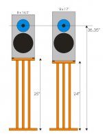
I think the speaker stands @ 24" are more common. And yes, thanks for the reminder about the couch I have 🙂 It sits higher so the ear is at 38". My couch is a piece of ****, anyway!
Now I have to buy a new #@%$ing couch too. You have made a mess of my life 🙂
Now I have to buy a new #@%$ing couch too. You have made a mess of my life 🙂
May I suggest DIY-ing a couch out of a timber frame with
separate seat and back made out of polyurethane foam mattress
that can surve as a double bed? The upholstery might be anything
skin friendly.
separate seat and back made out of polyurethane foam mattress
that can surve as a double bed? The upholstery might be anything
skin friendly.
Heya!
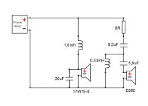
I ordered the parts you suggested for a crossover but I just have a small question: shouldn't eh 5.6 go where the 8 is and vice versa?
I ordered the parts you suggested for a crossover but I just have a small question: shouldn't eh 5.6 go where the 8 is and vice versa?
Attachments
Last edited:
I've implemented the crossover and I really like what's happened to the midrange. Thanks for that. On the other hand, a lot of the upper-octave "shimmer" isn't there. Would you recommend that I lower the inductor to, say, 0.15 mh?
Lowering to 0,15 mH would have pushed the high pass slope
to a higher XO point which has no potential of improving the
upper HF spl. If anything, then reduce the series resistor gradually.
to a higher XO point which has no potential of improving the
upper HF spl. If anything, then reduce the series resistor gradually.
The SPL of the tweeter is perfect. It's just the upper octave of the tweeter itself. Any other ideas?
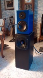
Decent paint job on the cabinets. What do you call these, blue ocean? 🙂
Did the filter mods bring any improvement?
Did the filter mods bring any improvement?
The color is called "Dress Blues". It's a Dulux colour.
I decided to start over with the crossover. Chris from Solen suggested this make-up. At present, I am just running the 5.6mfd, 8 ohms and 0.33 mh. it's a little hot on the bottom end of the tweeter so I think I am going to add 17mfd past the coil today. The 1.3mh coil he suggests seems really odd to me.
I have 0.33, 0.39, 0.69, 0.75 and 1mh available.
The crossover for the bass driver is fine. I am not running his because I can tell already that it would be hotter than hell in the midrange. As we discussed before, there's nothing I hate more than hot midrange.
Attachments
Last edited:
Chris gave you calculator values with no regard to baffle step and time
alignment. BW2 on woofer, LR2 on tweeter. You need a 3rd order
electrical on TW unit to get the phase right. I've had my share of painful
voicing the D260's and these were dented and not the same units, so
I have 2 different filters.
alignment. BW2 on woofer, LR2 on tweeter. You need a 3rd order
electrical on TW unit to get the phase right. I've had my share of painful
voicing the D260's and these were dented and not the same units, so
I have 2 different filters.
Last edited:
He has suggested raising the shunt inductance. I am thinking this is going to take me a step backward. The upper top end of the tweeter is great. The issue is at the bottom end (of the tweeter). I am thinking I will raise the series capacitance making it a 3rd order. So it would be:
5.6mfd
0.33mh (or, 0.39, 0.69, 0.75, 1mh)
16mfd
8.2ohms.
Tweeter wired back in phase.
Is this the direction you would go in?
An online calculator calls for 5.6uf and 0.75mh (out of phase tweeter). I don't think this is the answer, at all.
5.6mfd
0.33mh (or, 0.39, 0.69, 0.75, 1mh)
16mfd
8.2ohms.
Tweeter wired back in phase.
Is this the direction you would go in?
An online calculator calls for 5.6uf and 0.75mh (out of phase tweeter). I don't think this is the answer, at all.
Last edited:
Without measurements there is not much hope to resolve the voicing issue.
It's not the same where you put the padding resistor. The graph is a sim of
a tweeter with exactly the same XO filter, only difference being the placement
of a resistor. Black line=after XO filter, grey = before. Settle for caps and
inductor the way you think is good and change the resistor value and its
placement to your taste.
Attachments
- Status
- Not open for further replies.
- Home
- Loudspeakers
- Multi-Way
- 17W75 D260