This is the S-5 k-16LS kit amplifier with CXPP25-8K output transformers. It's a PPP design and I wish I had transformers that had 4 ohm taps. I previously looked at rebuilding it as a 3 pair output to lower output impedance. Edcor says 120mA max AC+DC , but never specified on B+ or per plate lead. Others have asked and not gotten answers. I decided that 120mA on the B+ was unlikely since Hammond rates per plate lead and you'd need pretty high volts to get 25W with 120mA total.
I decided to do some testing. There is currently 100mA total on the B+, so 25mA a tube. Changing the cathode bias resistor experimentally I increased it to 163mA and distortion went down. So I figure that the core isn't saturating, and probably won't melt the winding. Transformers never warmed up before.
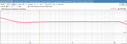
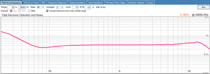
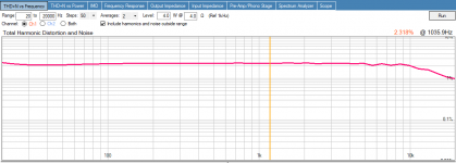
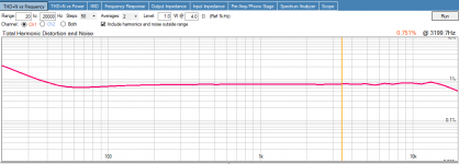
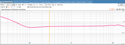
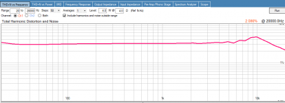
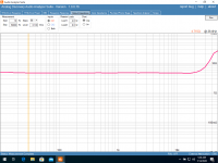
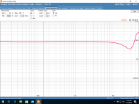
Here is the test data for this amp since I've never seen the data before. Of course the output transformers are upgraded, and no measurements were needed to know the Edcor was better in the bass frequencies. It's wired in UL mode. I was told that 20% UL taps would be better than the 40% with these tubes, but I have(kinda like I have 4 ohm speakers) 40% taps. This lowers output impedance, right?
I'll try to post test data with old transformers, and the Edcor without UL later.
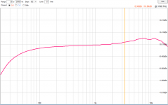
Frequency response at default .1Vrms output. There is a decimal point in the db number 😉

Frequency response at approximately 4 watts, but I'm not sure if this "level" is in or out now.

1 Watt into 8 Ohms 100mA

4 Watts into 8 Ohms 100mA

1 Watt into 4 Ohms 100mA

4 Watts into 4 Ohms 100mA

1 Watt into 4 Ohms 163mA

4 Watts into 4 Ohms 163mA

Schematic

I decided to do some testing. There is currently 100mA total on the B+, so 25mA a tube. Changing the cathode bias resistor experimentally I increased it to 163mA and distortion went down. So I figure that the core isn't saturating, and probably won't melt the winding. Transformers never warmed up before.
Here is the test data for this amp since I've never seen the data before. Of course the output transformers are upgraded, and no measurements were needed to know the Edcor was better in the bass frequencies. It's wired in UL mode. I was told that 20% UL taps would be better than the 40% with these tubes, but I have(kinda like I have 4 ohm speakers) 40% taps. This lowers output impedance, right?
I'll try to post test data with old transformers, and the Edcor without UL later.
Frequency response at default .1Vrms output. There is a decimal point in the db number 😉
Frequency response at approximately 4 watts, but I'm not sure if this "level" is in or out now.
1 Watt into 8 Ohms 100mA
4 Watts into 8 Ohms 100mA
1 Watt into 4 Ohms 100mA
4 Watts into 4 Ohms 100mA
1 Watt into 4 Ohms 163mA
4 Watts into 4 Ohms 163mA
Schematic
Attachments
-
 Responce.1Vrms.png16.3 KB · Views: 352
 -
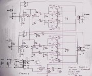 k-16ls - schematic.jpg89.3 KB · Views: 413
 -
 4W4OHM163mA.png19.1 KB · Views: 335
 -
 1W4OHM163mA.png18.9 KB · Views: 65
 -
 4W4OHM100mA.png19.1 KB · Views: 322
 -
 1W4OHM100mA.png19 KB · Views: 333
 -
 4W8OHM100mA.png18.8 KB · Views: 331
 -
 1W8OHM100mA.png19.2 KB · Views: 356
 -
 Responce4Vrms.png23.1 KB · Views: 321
So removed UL and went back to pentode operation and tested again. Results are up a little and down a little depending on power level.
1 Watt 4 Ohms in pentode mode.

4 Watts 4 Ohms in pentode mode.

Unless I'm missing something I'm going to build the 3 pair PP amp with fixed bias. Should lower my output impedance some to closer to the speakers. If I stay at 25mA per tube I'll be under the 163mA I tested before and with it'll be easier to adjust bias currents for more testing. I can go up to 40mA each and get the 120mA per side I think is safe with this transformer.
Cory
1 Watt 4 Ohms in pentode mode.
4 Watts 4 Ohms in pentode mode.
Unless I'm missing something I'm going to build the 3 pair PP amp with fixed bias. Should lower my output impedance some to closer to the speakers. If I stay at 25mA per tube I'll be under the 163mA I tested before and with it'll be easier to adjust bias currents for more testing. I can go up to 40mA each and get the 120mA per side I think is safe with this transformer.
Cory
Attachments

A 6005 Beam Power tube has a very high plate resistance, rp, of about 50,000 Ohms.
Going from a pair of push pull tubes, to a Quad of push pull tubes, and then to 6 tubes, reduces the output impedance somewhat.
The tubes are wired in Beam Power mode, the highest rp they can have.
The Global Negative Feedback lowers the output impedance far more than doubling or tripling the output tubes.
One thing I notice in the schematic is that there is no provision to know if the tubes are all at the same quiescent current (probably not).
And there is no provision to know if the total quiescent current in Push is the same as the total quiescent current in Pull (probably not).
If the total quiescent current on the output transformers plate connections are not matched, you get early saturation of the laminations, with all the problems that brings.
Tubes that are "Matched" at one set of plate current, screen voltage, and bias voltage, are often poorly "Matched" at the plate current, screen voltage, and bias voltage in your amplifier.
It seems like your graphs show pretty good performance, you may have been lucky on the matched currents.
Try wiring the tubes in triode mode, that will lower the plate resistance, rp.
Of course, you will get less power out. but trying that is easy, you already have the 200 Ohm screen resistors, just remove the ends from the screen B+, and connect to the plates. You may have to increase the resistance of R10 to keep the B+ at the input tubes the same (without the screen current on the B+, the voltage will go up at R10, because R26 no longer has screen current through it.
You might like the sound of triode wired, or you may not.
If I was to design a 'parallel tubes' push pull amplifier, the very first thing I would do is:
Use Individual Self Bias Resistors, and Individual Bypass caps across each resistor.
Self Bias tends to make tube currents match much better than what your circuit does.
Bias Resistor = 150 Ohms x the number of tubes.
4 tubes, use 600 Ohms for each cathode.
6 tubes, use 900 Ohms for each cathode.
You can measure the voltage across each resistor and see if the currents are matched.
Remember, the more current you have in the output transformer, the more a small percentage of current in-balance will cause core saturation.
Note: Your schematic does not show Ultra Linear connections. What else is different than the schematic?
It is hard to analyze a circuit when there is not enough information.
And yes, Ultra Linear does reduce the plate impedance, rp; But not nearly as much as Beam Power Triode Mode does.
Think of it this way:
Beam Power Mode = 0% UL
Ultra Linear Mode = x% (the same as the UL tap's rated %)
Triode Wired Mode = 100% Ultra Linear.
Just a reasonable illustration.
I design and build single ended and push pull amplifiers with Ultra Linear Mode and with Triode Wired Mode.
Happy mods! happy listening!
Last edited:
@6A3sUMMER Thanks for taking the time!
Sorry for the lack of information, I was trying to keep it short enough to read. I wanted to give some information on this kit as I've never seen test data, and many dislike it. Also wanted verification that Edcor's 120mA couldn't be on the B+ lead
, or it is very conservative.
The only change to the schematic was hooking the UL taps to the screen resistors instead of B+ and upgrading to the Edcor transformers, that is the schematic that came with the kit. It's a PCB design so big changes are hard to make. I think will try triode connection. Minimum experiences say I won't prefer it. Getting a little more power out of it was part of why I wanted to add another set of tubes.
You are correct there is no way to balance the current, or even measure it. Individual resistors are an option, but makes it a lot harder to play with bias settings. Either change will mostly likely be a new point to point with a few boards mixed in.
Now for my lack of understanding, and confusion to show up. I understand the impedance ratio of the transformer. And that tubes have listed data saying where they are best at. Datasheet says for PP 10K plate to plate, by 2 pairs that makes 5K, moving to 3 pairs is 3.3K. I have a 5K to 8 ohm transformer, with a 4 ohm speaker that's 2.5K. The book says lowest distortion is at 6K, which I assume would be 12K in PP. Also raising the plate voltage lowers the impedance some.
Does changing to triode, raising the voltage, or increasing NF effect the ideal impedance as far as distortion goes? After writing this I assume it does. I still don't have my head wrapped around everything involved with how tiode, UL, pentode and the output transformer are intertwined. I guess the function of triode mode makes good sense to me. Plate impedance of 5K and resistance of 50K is confusing. Is this related to the amount that the resistance 'can' change? I guess that is the third reason to build an amp is so I have access to modify it more and experiment. Any suggested reading?
Output impedance in UL

In pentode

Thanks again
Cory
Sorry for the lack of information, I was trying to keep it short enough to read. I wanted to give some information on this kit as I've never seen test data, and many dislike it. Also wanted verification that Edcor's 120mA couldn't be on the B+ lead
, or it is very conservative.
The only change to the schematic was hooking the UL taps to the screen resistors instead of B+ and upgrading to the Edcor transformers, that is the schematic that came with the kit. It's a PCB design so big changes are hard to make. I think will try triode connection. Minimum experiences say I won't prefer it. Getting a little more power out of it was part of why I wanted to add another set of tubes.
You are correct there is no way to balance the current, or even measure it. Individual resistors are an option, but makes it a lot harder to play with bias settings. Either change will mostly likely be a new point to point with a few boards mixed in.
Now for my lack of understanding, and confusion to show up. I understand the impedance ratio of the transformer. And that tubes have listed data saying where they are best at. Datasheet says for PP 10K plate to plate, by 2 pairs that makes 5K, moving to 3 pairs is 3.3K. I have a 5K to 8 ohm transformer, with a 4 ohm speaker that's 2.5K. The book says lowest distortion is at 6K, which I assume would be 12K in PP. Also raising the plate voltage lowers the impedance some.
Does changing to triode, raising the voltage, or increasing NF effect the ideal impedance as far as distortion goes? After writing this I assume it does. I still don't have my head wrapped around everything involved with how tiode, UL, pentode and the output transformer are intertwined. I guess the function of triode mode makes good sense to me. Plate impedance of 5K and resistance of 50K is confusing. Is this related to the amount that the resistance 'can' change? I guess that is the third reason to build an amp is so I have access to modify it more and experiment. Any suggested reading?
Output impedance in UL
In pentode
Thanks again
Cory
Attachments
1. Plate impedance, rp, is in parallel with the output transformer primary.
In Beam Power Mode (and in Pentode Mode for pentodes), most of the power is sent to the 5k transformer and from there to the load (speaker), very little power is used up by rp.
But damping factor is low. Each rp is 50k, and 1/2 of each output transformer primary is 1250 Ohms; 1/2 winding is 1/4 impedance (1/4 of 5k). But in Class A when both tubes are conducting, it is as if two 50k rp's (25k) was in parallel with 1250 Ohms). 1,250/2,5000
That gives a very low damping factor of only 0.05.
And the gain of the output tube is the tube transconductance, Gm, times the load impedance, which is quite high.
The fix for the low damping factor is to use lots of negative feedback, and the damping factor is increased.
Beam Power Mode and Pentode Modes give the most power out, so little power is wasted in in the plate impedance, rp.
2. Beam Power (and Pentodes) that are wired in Triode Wired Mode, have the lowest plate impedance, rp. And the gain is lowest too. A 6BQ5 plate impedance might be as low as 1500 Ohms. In Class A, we effectively have 1500 Ohms/2 in parallel with 1250 Ohms (1/2 primary).
1500/2 = 750 Ohms. 1250/750 = 1.67. The damping factor, DF, is now 1.67, much much higher than the Beam Power'sDF of 0.05. And . . . we have not even used any negative feedback. Negative Feedback will increase the damping factor.
But, we have the low plate impedance, rp, in parallel with the primary impedance.
Much of the power is used up by the Triode Modes rp, so there is less power going on to the output transformer, and so less power to the load (speaker).
3. Ultra Linear Beam Power, and Ultra Linear Pentode Modes are between the extremes of the two above operating modes. Medium rp, medium power, medium gain, and medium damping factor.
The UL tap % determines the rp, power, gain and damping factor.
But again, Negative Feedback increases the damping factor.
(True Ultra Linear is a very specific UL tap %, any other % value does not make it real Ultra Linear).
Medium rp uses up less power than triode mode, and uses up more power than Beam Power or Pentode modes.
Do not quote me on this, but I think that most smaller Beam Power tubes and most smaller Pentodes (6AQ5, 6BQ5, 6V6, and EL84) usually are truly UL at somewhere between 20 and 30% UL taps.
And I think that most larger Beam Power tubes and most larger Pentodes (6L6, 7591, KT66, KT77, KT88, and EL34) are truly UL at about 40% UL taps.
Last edited:
You should aim for no more than 2 ohms of output impedance on the 8 ohm tap from an amp like this. I would adjust the feedback network to get there, then restart the measurements.
1. Plate impedance, rp, is in parallel with the output transformer primary.
Do not quote me on this, but I think that most smaller Beam Power tubes and most smaller Pentodes (6AQ5, 6BQ5, 6V6, and EL84) usually are truly UL at somewhere between 20 and 30% UL taps.
And I think that most larger Beam Power tubes and most larger Pentodes (6L6, 7591, KT66, KT77, KT88, and EL34) are truly UL at about 40% UL taps.
Again, thanks for your time responding. I didn't want to reply until I had something intelligent to say, actually I'm not sure that I do yet. But you got me to thinking and reading in ways that have helped. The plate impedance being in parallel with the output tube threw me pretty bad, searching around I found an explanation that I can grasp. You are correct that the 6005 should have an UL tap at 20%, they are very close to a 6v6 tube according to the datasheet, just with different max values. I'm still reading and working on projects trying figure this all out. Built a power supply for experiments ect. Still planning to build the amp as planned with fixed bias as it's easier to experiment with.
Originally I had the conception that load impedance was tied to distortion as it was graphed in the tube data sheet. This was the primary reason for trying to lower the output impedance. My limited testing showed that also heavy tied to bias point. The other reason for the building the amp is I have 25W transformers and would like to get a little more head room. It's also a learning exercise as I have a pair of ESL speakers and would someday like to build a couple high powered monoblocks.
I hate to even bring up damping factor and feedback as I've seen some discussion on it go a little crazy. I understand using feedback to flatten the frequency response of the amplifier out for the SS world. But my reasoning is that it should be kept to a minimum. My amplifier is pretty flat into a dummy load, if I increase FB and make it more of a pure voltage source, then that horrible impedance graph of my speakers starts to effect the amplifier more. In my, probably flawed, logic the amplifier now wants to be more of a power source and flatten the line out.
On the question I'm trying to get my head around, my inability to form the question says I don't understand it yet, but I'm going to try. Did I get this right?
The Rp of the tube is due to the effect the plate voltage has on the plate current. Having more effect on a triode than a pentode or beam. So if the impedance on the output is lower current flows to the plate easier and less voltage drop at the plate, so plate current is higher. This would have little effect on the pentode or beam tube. If the impedance on the output is higher current flows less easily to the plate and the voltage drops, which lowers the plate current. This would have little effect on a pentode or beam.
So to follow this logic. The impedance load of the speaker has a much higher effect on a triode than a pentode. Damping factor would effect triodes more than Pentode or UL amps.
Did I figure that correctly? I understand a bit more, maybe, but not any closer than my initial experiment and see plan. Time to keep reading, working on my math re-education, and need to devote some time to kicad simulation with tube models too.
Thanks again
Cory
Just estimates:
EL84 Pentode mode, rp 18k
EL84 UL mode, rp 4 to 10k (depends on % tap, 40% 26% respectively).
EL84 Triode mode, rp 1.7k Ohms
Negative feedback lowers the Effective rp than the numbers above.
(which is why high impedance pentode rp almost always requires negative feedback).
Some Triode wired amps work well with no negative feedback.
UL is in-between.
The lower the rp, the higher the damping factor.
The higher the damping factor, the less effect the loudspeaker load has on the amplifier.
I do not know the estimated numbers for the 6005 tubes.
Start with rp 50k for Pentode mode, and the UL mode rp will be lower, and the Triode mode will be the lowest rp.
UL 25k?
Triode mode 5k?
Just estimates.
Similar to the ratios of the EL84 modes.
Does that make sense?
Last edited:
Does that make sense?
Yes it does, I didn't mean to imply it didn't. Lots of stuff to learn still, trying to reason through the whys and hows.
Thanks
Cory
- Home
- Amplifiers
- Tubes / Valves
- 16LS, CXPP25-8K, THD&Freq plots. Bias adjustment and questions.