Perhaps just D1 put in opposite direction?Try adding another diode in parallel with D1 but in the opposite direction 🙂
I will remove RC, and do make some test, thank you Wahab.
Hi Apex!
what happend to your kelvin amp? no further post. Is it final module or need correction in RC as mentioned. please update😕
i like to build this for my new 12" subwoofer😀
Thanks
vijay Daniel
It is final module, I made 120 module in a year and a half before post, everyone work ok. RC shunt compensation work ok in real world.Hi Apex!
what happend to your kelvin amp? no further post. Is it final module or need correction in RC as mentioned. please update😕
i like to build this for my new 12" subwoofer😀
Thanks
vijay Daniel
Regards
Last edited:
It is final module, I made 120 module in a year and a half before post, everyone work ok. RC shunt compensation work ok in real world.
Regards
Thankyou Mile!
i will go head in making PCB😀
Vijay
Do you have active x-over for subwoofer?Thankyou Mile!
i will go head in making PCB😀
Vijay
Regards
Do you have active x-over for subwoofer?
Regards
No i have planed to connect to sub out from my DVD player.😕
Vijay
Crossover and switching distortion that is audible may not be visible on a scope measurement you really need a distortion analyser of some sort. Switching and crossover distortion does not seem to affect some peoples enjoyment of music. For others, me included, it sounds like scratching glass which is why there is a valve and class A contingent in this conf 🙂.
As far as I am aware Peavey amps are used for guitars so will not have much HF content and if they did the bass unit would not reproduce it anyway so there is no point in trying to reduce it.
As far as increasing the bias current it does make sense if you are one of the lucky or unlucky few, the cost of getting rid of those distortions is high!, that finds switching and crossover distortion annoying. As the bias current increases the switching and crossover point occurs at higher power levels and the louder the music the less sensitive the ear is to distortion.
I agree. I did some experiments and posted a while back in this thread starting here, using an HEC based output stage follower. Observing the output vs the error signal, the error signal clearly shows the Gm drop vs drain current as the fet approaches cutoff as having a very steep slope. It takes quite a bit more bias to really reduce this effect; even 300mA is not enough but puts the slope of the error signal within means of greatly reducing the crossover distortion to a point of negligence. This is one of the worst trade-offs for using mosfets in class AB. Too much bias is not really good either and can cause Gm doubling, having similar effect. There is an optimum bias for any pair of outputs used in this fashion and it greatly depends on the specific devices. I find higher conductance fets seem to like a bit more bias.

That's ok sub out come thru sub x-over in DVD player.No i have planed to connect to sub out from my DVD player.😕
Vijay
That's ok sub out come thru sub x-over in DVD player.
Hi apex,
Do you have any seperate x over ciruit for sub pre?🙄 i want to connect left + right channel to X over and output to subwoffer amp😀. Because DVD player sub woofer out is not comming in all DVDs. I think some AC3 DTS settings differs for different DVDs😕
Last edited:
Subwoofer filter have low cut on 30Hz, boost +4dB up to 100Hz, also have level and X-over frequency adjust from to 80-250Hz, stereo inputs from speakers and stereo inputs from line signal, output for amp... like on pics with Kelvin amp (post #31).Hi apex,
Do you have any seperate x over ciruit for sub pre?🙄 i want to connect left + right channel to X over and output to subwoffer amp😀. Because DVD player sub woofer out is not comming in all DVDs. I think some AC3 DTS settings differs for different DVDs😕
Subwoofer filter have low cut on 30Hz, boost +4dB up to 100Hz, also have level and X-over frequency adjust from to 80-250Hz, stereo inputs from speakers and stereo inputs from line signal, output for amp... like on pics with Kelvin amp (post #31).
Hi Apex !
Thanks for your replay. your X over PCB looks small and incredable😀 with all those controls to vary frequency.🙂 Can you post your X over Schematic and layout😀
Thanks
vijay
I think all my PCBs looks incredable 😎Hi Apex !
Thanks for your replay. your X over PCB looks small and incredable😀 with all those controls to vary frequency.🙂 Can you post your X over Schematic and layout😀
Thanks
vijay
Regards
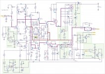
Try adding another diode in parallel with D1 but in the opposite direction
what is the purpose of these two opposite-parallel diodes ??
The diodes reduce the amount of time that the output remains stuck to the rails after clipping. This is achieved by preventing the voltage across C3 from deviating too much from what it should be when the amplifier is into linear operation.
Without diodes, C3 is charged and discharged in an uncontrolled way during clipping, and the output will remain stuck to the supply rails until the voltage returns to the normal value (which takes some time).
Without diodes, C3 is charged and discharged in an uncontrolled way during clipping, and the output will remain stuck to the supply rails until the voltage returns to the normal value (which takes some time).
Thank's to Eva, schematics is in post #31. This is condition of overload with hard cliping (more than 10%THD), not usual home listening.The diodes reduce the amount of time that the output remains stuck to the rails after clipping. This is achieved by preventing the voltage across C3 from deviating too much from what it should be when the amplifier is into linear operation.
Without diodes, C3 is charged and discharged in an uncontrolled way during clipping, and the output will remain stuck to the supply rails until the voltage returns to the normal value (which takes some time).
Regards
Last edited:
and what if i dont use C3-R5??most schematics i have seen, dont have this network.
will i have to use these diodes again?
will i have to use these diodes again?
Don't change anything on this schematics, it just look like "most schematics" for diy, but take a better look, this is high performance amplifier, and you must use C3-R5, don't try to make it simpler, it is imposible if you want to have better amp than "most".and what if i dont use C3-R5??most schematics i have seen, dont have this network.
will i have to use these diodes again?
Regards
C3 and R5 are part of a pole-zero compensation system.
The advantage of pole-zero compensation is higher open loop gain at mid-high frequencies, which translates into lower high-frequency distortion and lower output impedance, without any substantial degradation in stability. The usual rise in output impedance and distortion above 1khz in traditional amplifiers is moved upwards, it does not start until a higher frequency (may be as high as 20khz resulting in flat THD and constant damping factor, which makes the amplifier closer to "ideal").
Pole-zero compensation is rarely used in DIY amplifiers because it's a bit more complex than the traditional dominant pole compensation and harder to implement for people with no knowledge about feedback control loop theory (or even without an oscilloscope).
- Home
- Amplifiers
- Solid State
- 150W MOSFET Amplifier with IRFP250x2