too many unknowns
Since we don't know the focal lengths of the individual lenses that are in the 450 mm fl triplet, we can't really say what happens to the light inside it. If the lenses were +450 mm fl, -450 mm fl, +450 mm fl, then I think the first lens would refract rays at the edge by about 8 degrees. But then the middle lens would refract them back by some amount.
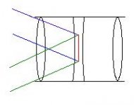
Instead of guessing about what happens inside the triplet, my estimate is based on the size and directions of the light paths coming from opposite corner LCD pixels for this particular application. In the drawing below, the blue lines represent the path of all of the light going through an LCD corner pixel. (I know that this is the path, because if I remove the triplet and put a piece of white paper where the center lens would go, I can see the focussed 60 mm long arc image.) The width of each light path will actually be a little bit smaller than 60 mm inside the middle lens, because of refraction by the first lens.
The green lines represent the path of all of the light going through the opposite corner pixel of the LCD. If we send light along these paths, at least we know it will get into the lens and most of the light from each path will get converged to a single spot on the screen 10 feet away. If we want to know exactly what happens inside the triplet, then we need to know the lens materials, the 6 surface curves, and the spacing. Then we can put all of that in a ray tracing program to make some better predictions.
But maybe all of this is not necessary: If anybody reading this has one of these triplets, they could use a laser pointer to find the maximum field angle through the lens in just a minute or two, and then post the result here!
Since we don't know the focal lengths of the individual lenses that are in the 450 mm fl triplet, we can't really say what happens to the light inside it. If the lenses were +450 mm fl, -450 mm fl, +450 mm fl, then I think the first lens would refract rays at the edge by about 8 degrees. But then the middle lens would refract them back by some amount.
Instead of guessing about what happens inside the triplet, my estimate is based on the size and directions of the light paths coming from opposite corner LCD pixels for this particular application. In the drawing below, the blue lines represent the path of all of the light going through an LCD corner pixel. (I know that this is the path, because if I remove the triplet and put a piece of white paper where the center lens would go, I can see the focussed 60 mm long arc image.) The width of each light path will actually be a little bit smaller than 60 mm inside the middle lens, because of refraction by the first lens.
The green lines represent the path of all of the light going through the opposite corner pixel of the LCD. If we send light along these paths, at least we know it will get into the lens and most of the light from each path will get converged to a single spot on the screen 10 feet away. If we want to know exactly what happens inside the triplet, then we need to know the lens materials, the 6 surface curves, and the spacing. Then we can put all of that in a ray tracing program to make some better predictions.
But maybe all of this is not necessary: If anybody reading this has one of these triplets, they could use a laser pointer to find the maximum field angle through the lens in just a minute or two, and then post the result here!
Attachments
Re: too many unknowns
I have a laser pointer, and an identical looking lens... how can I measure the fov with a laser pointer?
Guy Grotke said:
But maybe all of this is not necessary: If anybody reading this has one of these triplets, they could use a laser pointer to find the maximum field angle through the lens in just a minute or two, and then post the result here!
I have a laser pointer, and an identical looking lens... how can I measure the fov with a laser pointer?
ROX,
You are thinking but you are in error. The refraction caused by the lenses system is taken into account as is part of the chromatic correction and these issures are taken into account when the FOV is stated.
All light is refracted by all of the lenses in differing amounts. The light being refracted does not lessen the stated FOV because the designed FOV assumes that such things are occuring and the lens correction is what takes this into account. The FOV of a lens system is not based on simple geometry but we have used simple geometry to show how the light cone of the fresnel will fit in the aperature of the lens. As long as the field fresnel light cone is within the FOV of the lens there will be little wasted light output. But this is a seperate issue from the objective lens system's FOV.
The FOV of the objective lens system is not based on such simple geometry. It is determined by the corrected refracted indexes and dispersion of the combined lens system. Each lens element is a different glass type and shape and spacing from the others lenses. This is what is used to correct for the different amounts of refraction at different light frequencies.
Repeat, the stated FOV is an engineered level of performance and assumes that there is refraction therefore the stated FOV is what it is unless the company was lying to you. But what they have stated is inline with what Guy has measured and what common lens design sense and experience indicate it shold be.
Hezz
UPS should be delivering this lens to me tomorrow! (It only took 45 days or so for DIYPC to ship it to me  )
)
I have been following this discussion for quite some time and will be happy to do some experimentation in attempts to help resolve these issues once and for all.
I have a laser pointer around somewhere also...
)I have been following this discussion for quite some time and will be happy to do some experimentation in attempts to help resolve these issues once and for all.
I have a laser pointer around somewhere also...
very easy to measure field angle
You just lay the lens on its side on a table with the screen 10 feet away, then point a narrow laser beam through it. You should see a laser spot on the screen. (Use some masking tape or a couple of small paperback books to hold the lens in place.)
Create a line on the table (on paper maybe?) that is perpendicular to the lens central axis, and 530 mm back from the center of the lens tube. Then you can move the laser pointer (with its tip on that line) as you keep it pointing at the center of the lens. (Not the center of the first lens surface, but the center of the entire lens tube.)
When the screen spot dissappears, you may have gone past the maximum field angle. You can try and move the laser direction a bit on the first lens surface to see if you can get the screen spot to reappear. If not, then you have gone past the maximum angle. Move the laser pointer back along the line until the spot just reappears on the screen. Measure the angle of the laser beam relative to the central axis. If you don't have a protractor, you can just measure the distance of the laser pointer tip from the central axis along the 530 mm perpendicular line. If that is more than 8.5 inches, this triplet will work fine for a 17" LCD.
Tip: Make sure the laser pointer is at the same height above the table as the middle of the triplet, (ie. 67.5 mm?)
Hezz said; "The FOV of the objective lens system is not based on such simple geometry. It is determined by the corrected refracted indexes and dispersion of the combined lens system. Each lens element is a different glass type and shape and spacing from the others lenses. This is what is used to correct for the different amounts of refraction at different light frequencies"
I agree with you Hezz, SO the test Guy Grotke described (my friend did it also with his 135 tirplet and my laser) i would say it is not the Field angle, this test would show the max critical light angle, mean the last light angle (light stop angle), but i believe the fov is smaller because it is not geometrical defined but the aperture where the focus, light intensity, aberrations... are the minimal expected by design as hezz said.
I still have not received the reply from manufacturer about the field angle 24 (12+12) or 48 (24+24) but i think the spec they will give will be more acurate than any test we could do.
Rox,
I think that they may not respond to you because it is common knowledge that the stated FOV is measured from the lens axis to the furthest corrected light angle. So if they told you that it is 24 degrees then the total usable imaging angle is twice that number.
I thinks Guys test was still reasonably accurate in describing the approximate FOV. It would'nt make much sense from a design point of view to make a lens system this large have only a 24 inch total usable imaging angle because it would have little utility except in the case where a huge amount of light ( several kilowatts) had to be put through the lens at a narrow angle.
Hezz
well, if they have told me that the angle is X, then they have not problem telling me where is the angle defined 😀.
I still have no reply, but will tell you soon. Just wonder, have you ever seen corner to corner focused image with 15"?
this is focused ok at center but i would not say it is "corner to corner focus" check it.
http://img.photobucket.com/albums/v629/diyeitor17/DSC01328b.jpg
I still have no reply, but will tell you soon. Just wonder, have you ever seen corner to corner focused image with 15"?
this is focused ok at center but i would not say it is "corner to corner focus" check it.
http://img.photobucket.com/albums/v629/diyeitor17/DSC01328b.jpg
laser test
The laser beam used in the test I described will be a very narrow beam, so it will let you determine the maximum angle at which 100% of the light in a particular ray will get through the lens. Once you know that angle, then you can use it to see how wider beams (ie. all the light from a corner LCD pixel) will pass through the lens.
You can refer to the last drawing I included in a post. The laser will show you if the upper edge of the corner-pixel beam can get through the lens. Then you can rotate the laser slightly to see if the lower edge of that beam will also get through the lens. If both edges of the beam get through the lens, then it will work fine for a 17" LCD projector.
Also, I think that most lens designs are made so the edges and the center have "good enough" performance. Some distance part way between the edges and the center, the performance will be the best. But that particular distance does not define the FOV. The full field of view uses much more of the lens.
looks like it is cut off at the corner
Isn't that image from your friend's projector that uses a 330 mm fl field fresnel? That probably has more to do with the poor corner appearance than the use of the 450 mm fl triplet.
gg
Isn't that image from your friend's projector that uses a 330 mm fl field fresnel? That probably has more to do with the poor corner appearance than the use of the 450 mm fl triplet.
gg
yes, it is my friends 135 native results with 330.
but could you show me better images of 15" with 135? people say they have " corner to corner" but never seen it.
I would like someone to prove it. JCB,could be one that could demostrate it. I would like to see close photos like this one i posted.
I really would like to check it is posible, nothing else.
about the laser test, it is the max angle the triplet can work on ok, but how can we know the field angle from there? i measured the 80 triplet with my laser and found it is 120 degrees, (60+60)
but it is known that the lens does not work very well with 17" so the field angle is much smaller than the max laser angle.
So what can we learn with 135 triplet laser angle?
Ok the 24 degrees are full angle, 12+12 so it is not 48 (24+24) as most of us would like to be.
it is 24 the specs of field angle this lens was designed for, it has been confirmed by manufacturer just now.
If large panels are going to be used with this lens, there needs to be some sacrifice with the focus on the corners.
Good luck with it.
it is 24 the specs of field angle this lens was designed for, it has been confirmed by manufacturer just now.
If large panels are going to be used with this lens, there needs to be some sacrifice with the focus on the corners.
Good luck with it.
Isn't that image from your friend's projector that uses a 330 mm fl field fresnel? That probably has more to do with the poor corner appearance than the use of the 450 mm fl triplet.
I agree on that and the majority of the time people have trouble with dim corners because their frensels are not flat or not matched to the projection lens. Or, their condenser is not right or the distance to the rear frensel from the source light is not correct to the rear frensels focal ect.
Heaps of things cause hot spots and dark corners, the projection lens is realy the last thing you take a look at.
As a rule of thumb in what ive found, the longer the projection lens barrel on a given set diameter, the shorter the field of veiw.
Trev🙂
ace3000_1 said:
I agree on that and the majority of the time people have trouble with dim corners because their frensels are not flat or not matched to the projection lens. Or, their condenser is not right or the distance to the rear frensel from the source light is not correct to the rear frensels focal ect.
Heaps of things cause hot spots and dark corners, the projection lens is realy the last thing you take a look at.
I think you are wrong there. The first thing to check should be the field angle from the triplet, if it is too small (24 degrees are very poor) do not try to have corner to corner focus there).
Mean the manufacturer does not recoment to work where the field angle is larger than 24 because it was not designed for this. Is that easy. Anyway i agree that the propper field fresnell would do better work.
Data: my friend after modifiyng the triplet, has much better focuse images but still is ussing 330 field fresnlell even with a larger focal triplet, how would you xplain it?
Data: my friend after modifiyng the triplet, has much better focuse images but still is ussing 330 field fresnlell even with a larger focal triplet, how would you xplain it?
I think thats obvious.......
I think you are wrong there. The first thing to check should be the field angle from the triplet, if it is too small (24 degrees are very poor) do not try to have corner to corner focus there).
No im not wrong, why would someone go out and buy a triplet for a large panel that has a 24deg FOV in the first place? Thats what would be wrong 😉.
I know what your trying to get at Rox and your talking from a different level of mind. Why would anyone go out and buy the wrong parts and try to make them work? thats kinda pointless in my eyes and why its important to do a full scale drawing in the first place to see what optical characteristics you need. Doing it the otherway is like a dog chassing its tale, you will be there forever trying to get things right.
If you want my honest opinion, the way we do things isnt the right way to go about it. Running a projector in full paralelle is the best way to have a perfectly focused image with even brightness, but unfortunatley doing that on our sized pannels would be pointless, costly and heavy. A 7inch lcd is still too big in my eyes, both for efficency and for image quality. A 1-2inch is ideal.
Trev🙂
then what do you think about the compatibility of 135 triplet and 15" lcd? (not to mention 135 triplet and 17")
I wouldnt buy it, if you only have 12deg per side thats kinda too small. I did rough rough scetch and i mean rough with 2 rulers measured 15 inches apart (i know thats not the width of the lcd but lets work on diagonal here) at one end, and measured up 450mm to a point. Then i got out a protractor and measured the deg per side, it requires about 20deg per side so you would need a triplet atleast with a 40deg FOV.
That triplet has a nice arperature, but the FOV sux. The OHP triplets he sells would give a better image i would suspect as their FOV is around 65mm (32.5mm per side) but the arperature is kinda small which in turn gives us limited focusing ability, and therfore you could get dark corners again on the OHP lens. If you use a frensel that has aspherically contorured groves the image may sufice but still wouldnt be perfect. The Vari triplet from Brainchild may work better though im not sure of its FOV. If it has a FOV larger then 50mm (combined) and an arperature of 100mm, then youve got it made (providing your using the right frensels).
Trev🙂
Realy on a lens that has a FOV of 12deg per side its only good for a projector run in a paralelle fashion, that would yeild great results.
Trev🙂
Trev🙂
i agree.
But brainchild has deleted this item thought. (there is not at store since couple of weeks)
I believe this 135 triplet needs to be done some sacrifice with the focus on corners when we have 15" even.
But brainchild has deleted this item thought. (there is not at store since couple of weeks)
I believe this 135 triplet needs to be done some sacrifice with the focus on corners when we have 15" even.
I believe this 135 triplet needs to be done some sacrifice with the focus on corners when we have 15" even.
Ya i agree, its probally relying on its large arperature to focus the sides not the FOV in which would make the corners smudged.
I was reading what you had to say in the other thread about having to see a 15inch lcd perfectly focused on the corners with this lens, i do agree with you, its kind of impossible. Some think that if its looks focussed it is focused, but get up close to the pixels and you will soon see that its not, well, its focused but smudged lol. Thats fairly normal in most of our setups, people dont like to admit this but its a fact of reality from using the optics we use currently available to us from diy online stores. Its also cos we arent running things in a paralle manner, the way we run our projectors isnt the best way in the imaging world.
Trev🙂
- Status
- Not open for further replies.
- Home
- General Interest
- Everything Else
- The Moving Image
- Optics
- 135mm long-throw lense kit from diylabs