I have conducted some more tests last night and this is what I noted: Ambient temp = 26°C
Eva was right in what she said in a previous post. The battery voltage at 100A is 11.5V. At the input to the CT on the transformer this had fallen to 10.76V. The volt drops were measured and apportioned out to the cabling, connectors and fuses respectively.
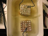
I ran the amplifiers at 252 wrms for 6 mins continously and observed that the transformer after this time had reached 82°C and the heatsink 55°C. By this time the battery had almost completely drained as the voltage at the terminals was 11.2V @ 82A of current drain. The input to the CT was then 10.24V and the under voltage protection had then kicked in.
The amplifiers all the while were fan cooled but not the PSU.
Any comments on the data above will be most valued. I need to know if the transformer temperature is too high.
Please see attached snubber design tip from RidleyEngineering. I hope I am not violating any copyright.
Eva was right in what she said in a previous post. The battery voltage at 100A is 11.5V. At the input to the CT on the transformer this had fallen to 10.76V. The volt drops were measured and apportioned out to the cabling, connectors and fuses respectively.
I ran the amplifiers at 252 wrms for 6 mins continously and observed that the transformer after this time had reached 82°C and the heatsink 55°C. By this time the battery had almost completely drained as the voltage at the terminals was 11.2V @ 82A of current drain. The input to the CT was then 10.24V and the under voltage protection had then kicked in.
The amplifiers all the while were fan cooled but not the PSU.
Any comments on the data above will be most valued. I need to know if the transformer temperature is too high.
Please see attached snubber design tip from RidleyEngineering. I hope I am not violating any copyright.
Attachments
I'd say that temperature is getting too high for a transformer. I believe that ferrites do not generally have very high Currie points. I wonder if thermal expansion could crack the core.
subwo1 I have checked on EPCOS site and noted that the curie temperature for N87 material > 210°C. I think my concern is that the insulation of the wire will create a problem especially the polyurethane ones.
EPCOS quotes that :
Core losses at 25 kHz, 200 mT, 100 °C is 57kW/m3.
Why would they quote at 100 °C if they don't expect the core to get that hot ?
EPCOS quotes that :
Core losses at 25 kHz, 200 mT, 100 °C is 57kW/m3.
Why would they quote at 100 °C if they don't expect the core to get that hot ?
Some cores have less losses at higher temperatures (to a point, of course). For example, my 3C90 core had less losses at 100ºC than at 40ºC.
However, 82ºC at 250W more or less is a bit high, I think. Perhaps excessive flux density?
If you provide the datasheet of your core and the number of primary turns, perhaps I can help.
Best regards,
Pierre
However, 82ºC at 250W more or less is a bit high, I think. Perhaps excessive flux density?
If you provide the datasheet of your core and the number of primary turns, perhaps I can help.
Best regards,
Pierre
Does the transformer run hot if left on with no load (other than the idle current of the amplifier)?
110C is relatively hot (I think most people try to keep the temperature rise in the core to ~40C above ambient) but if it doesn't go much higher and the wire's insulation can take the heat, the power supply should be reliable. The N87 material has the least loss at ~110C so the temperature of the transformer may level out at approximately that temperature.
I'd suggest running the amp as you would during normal service. There are lots of amplifiers that can't survive full power sine wave output. If this amp is not for commercial production, as long as it performs satisfactorily for listening to music at the levels you desire, the transformer may be OK.
You could always add a small fan to the PS or add a thermistor to the transformer to protect against high temperatures.
The transformer at idle (both amp modules on) is 3 deg higher than ambient.
I think that I should install a thermistor circuit just in case but am a little unsure at what temp should this kick in at.
I think that I should install a thermistor circuit just in case but am a little unsure at what temp should this kick in at.
I would set it to trip at ~120C. If it gets above 110C, the loss will begin to increase and the core will likely increase rapidly in temperature from there.
Have you played it at high volume with music, driving speakers?
If so, how hot did the transformer get?
Have you played it at high volume with music, driving speakers?
If so, how hot did the transformer get?
Thanks Perry.
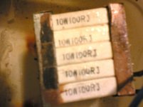
No I havent. I have played it with a sine wave at 1kHz into those resistor loads continuosly. At that point after 6mins the water in the container was almost boiling.
I dont have 4Ù speakers that have an rms rating over 250W.
I wonder if there are any car speakers that have such a high rms rating apart from subwoofers.
My intention is to drive an 8Ù 600W subwoofer (that I hope to acquire shortly) in bridge mode
Archimedes
I was working on my own SMPS, which is not that powerful. Could I see your schematic and/or your PCB?I would build one like yours.
I was working on my own SMPS, which is not that powerful. Could I see your schematic and/or your PCB?I would build one like yours.
Luka unfortunately I cannot give out the schematic as this is still a work in progress. I'd be more than willing to give you any tips though.
Archimedes
I would like to know next things:
How many turns on PRI and SEC of your transformer,
How many turns on input inductor,
How many turns on output inductor,
Sizes of yours cores,
Operating frequency at which SMPS runs
I would like to know next things:
How many turns on PRI and SEC of your transformer,
How many turns on input inductor,
How many turns on output inductor,
Sizes of yours cores,
Operating frequency at which SMPS runs
Pri 4+4 Sec 24+24
Input choke is 10uH +/-10 turns on T184-26
Output chokes are 100uH +/- 36 turns on T152-26
Freq is 32kHz
Input choke is 10uH +/-10 turns on T184-26
Output chokes are 100uH +/- 36 turns on T152-26
Freq is 32kHz
Get ready for some painful fingers and hands:
Each pri is made up of 6 x 1.9mm
Each sec is made up of 35 x .312mm
Each pri is made up of 6 x 1.9mm
Each sec is made up of 35 x .312mm
Look at the 1st or 2nd page of this thread. I have included a transformer calculator. You can play with the figures of the wire for both the pri and sec.
- Status
- Not open for further replies.
- Home
- Amplifiers
- Power Supplies
- 12V push pull SMPS