Bryan said:I was under the impression that I needed to properly rectify and smooth the voltage before the 317, is this not true?
Regulators typically achieve a reduction of 60-80dB in hum, so it's rare to need anything more than a simple reservoir capacitor, or perhaps LC.
What is the appropriate way to do this if you can not use a CRCRC... filter, just one cap in front of the 317?
Yes.
Why use CRCRCRC smoothing for a filament supply? The moment you draw any current, the voltage going to your 317 will collapse.
Could you help me understand this???
I've read of posts where people have used filtering before the regulator, how is this done?
Is the voltage colapsing at the regulator due to the voltage drop accross the resistors when the current is being drawn? That is, if I have 220 ohm resistors in the CRC filter, and I draw 0.3A, I would drop more volts than the rectified 12.6 volts can provide???
Bryan said:Is the voltage collapsing at the regulator due to the voltage drop accross the resistors when the current is being drawn? That is, if I have 220 ohm resistors in the CRC filter, and I draw 0.3A, I would drop more volts than the rectified 12.6 volts can provide???
You have it exactly right. In an HT supply, you can afford to drop 20V or so to achieve smoothing. Ideally, one would scale things for heater supplies, but the significant ESR (Equivalent Series Resistance) of an electrolytic capacitor means that RC smoothing doesn't work.
It's worth considering that pre-amplifiers with inputs for magnetic cartridges were traditionally made using AC heaters. In other words, you don't need a great deal of smoothing, and the reservoir capacitor plus regulator will do nicely.
However, a common-mode choke followed by 10nF capacitors to chassis before the regulator can be useful for preventing RF from reaching (and passing straight through) the regulator.
EC8010,
Thanks for the lesson! One of the major goals of this project was tol learn, and I am doing so at a great pace! Fortunately a couple caps and resistors are a small price to pay for the gain in knowledge😉
So, as far as common mode chokes are concerned, what type do you prefer/reccomend.
I'm looking at some from digikey, epoxy potted 10,000uH, 1.2 amp rating.
http://rocky.digikey.com/scripts/ProductInfo.dll?Site=US&V=197&M=CM1011-106
Thoughts?
Thanks,
Bryan
Pay attention, class!
You're welcome. Those chokes look fine. Bear in mind that at RF, a piece of wire is an inductor, so you want short wires to the chassis. (Short = 1/4")
You're welcome. Those chokes look fine. Bear in mind that at RF, a piece of wire is an inductor, so you want short wires to the chassis. (Short = 1/4")
Voltage Regulator Question
Well, things are progressing nicely!
I have to PS breadboarded, and I am just waiting for the iron so that I may power up the circuit.😀
It's kind of a weird feeling having everything ready to fire up, but no power....🙁 Well, I'll just leave that alone for now...
Anyway, to my question.
I currently have an 0A3 and an 0D3 in series, to provide me with a regulated 225 volts. Both tubes are bypassed with 0.047 ASC 200volt polyprop caps.
First, with the dropping resistor before the VR tubes, the value is chosen by the amount of B+ voltage necessary to drop, at the combined current through the VR's and the CCS-loaded plate, correct? Is in necessary to have the B+ at the VR tubes at 225 volts, or would 240 be OK?
Secondly, do I need to use a potential divider with the VR tubes to provide each tube with its strike voltage?
Thanks,
Bryan
Hi,
Those VR tubes will need some current to strike so a higher B+ is needed.
You need to take into account the current consumption of your stage + what the VR tubes need to be able to regulate.
No, you don't.
Cheers,😉
Is in necessary to have the B+ at the VR tubes at 225 volts, or would 240 be OK?
Those VR tubes will need some current to strike so a higher B+ is needed.
You need to take into account the current consumption of your stage + what the VR tubes need to be able to regulate.
Secondly, do I need to use a potential divider with the VR tubes to provide each tube with its strike voltage?
No, you don't.
Cheers,😉
Frank,
So, as long as the B + is above the added strike voltage of both tubes I should be fine?
Thanks,
Bryan
So, as long as the B + is above the added strike voltage of both tubes I should be fine?
Thanks,
Bryan
Hi,
As long as you stay within the current demands of the lot, yes, that would work.
Cheers,😉
So, as long as the B + is above the added strike voltage of both tubes I should be fine?
As long as you stay within the current demands of the lot, yes, that would work.
Cheers,😉
Hi Bryan
what kind of CCS are you going to use?
I also have build a 12B4A line stage but with a 6K anode resistor.Now I'm planning to build a better PSU and I'll put a phono stage in my project.
what kind of CCS are you going to use?
I also have build a 12B4A line stage but with a 6K anode resistor.Now I'm planning to build a better PSU and I'll put a phono stage in my project.
Why don't you go with tubes.
Couple of reasons...
Firstly, the Pimm CCS was reccomended to me by a more experienced builder.
Secondly, the availability of the PCB boards was convenient.
Thirdly, they have been tested and are apparently quite reliable, from what I have heard from other members. The board I have included a small trim-pot for adjustment of the current, which I was excited about, as I intend to try some different opperating points for the 12B4A.
Also, the added heat and size of additional iron/tubes is getting to the point where I may just have too much! Each channel, as of now, has 3 transformers, and two chokes! The PS (seperate chassis) will have 10 pieces of iron, and 8 tubes currently.
Tell me some more about your linestage... Do you like? What are your opperating points? Any "out of the box" approaches?
Best,
Bryan
I have build it without chassis.All in the air.Just to have a first approach before starting to build it.
It sounds too good!!!(thanks Brett).
I build it with
B+ 300V
Ia 30mA
Ra 6K
Vg -12,5V
Rk 410 bypassed with 220uF MKP
rp 950R
u 6,4
Bypassed has gain about 5,5 and Zout 820R.
It sounds too good!!!(thanks Brett).
I build it with
B+ 300V
Ia 30mA
Ra 6K
Vg -12,5V
Rk 410 bypassed with 220uF MKP
rp 950R
u 6,4
Bypassed has gain about 5,5 and Zout 820R.
GAK,
SWEET, I'm glad you like the 12B4A so much. My preamp's inspiration is from Brett's design as well. I plan to run CCS at about 30mA, at about -11.5 volts for starters, very similar to your points.
My PS is pretty solid (I hope), dual mono, with individual trannies for everything! LCLC. 300B+. Regulated fillaments. VR tubes...etc etc I think it should sound quite nice. I've heard nothing but good things from everyone with regard to this valve.
Wires are flying around on mine as well, and I hope to post some pics as soon as I get a digital camera! I expect the iron to arive today, so hopefully I'll see some glow tonight/tomorrow.
Bryan
Hey Guys,
Couple questions about my PS.
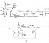
I hooked up the 375-0-375 transformer last night without the CT grounded/attached to anything, in place of the 300V transformer I have in my diagram below. Well, I blew some fuses. I think I may have shot one of my diodes behind the tube rectifiers... is this likely? They are the Cree 600V schottkies. How much current gets drawn through these?
I will try a few new things tonight, in order to get things working, but I was wondering if I could simply use the two 12AX4GTA's in a FWB, and omit the solid state diodes. For this application, I would earth the CT, and the negative rail of the PS after the rectifiers, correct?
With the tube hybrid, I dont earth the CT, and earth the negative rail of the PS after the rectifiers, right?

Couple questions about my PS.
I hooked up the 375-0-375 transformer last night without the CT grounded/attached to anything, in place of the 300V transformer I have in my diagram below. Well, I blew some fuses. I think I may have shot one of my diodes behind the tube rectifiers... is this likely? They are the Cree 600V schottkies. How much current gets drawn through these?
I will try a few new things tonight, in order to get things working, but I was wondering if I could simply use the two 12AX4GTA's in a FWB, and omit the solid state diodes. For this application, I would earth the CT, and the negative rail of the PS after the rectifiers, correct?
With the tube hybrid, I dont earth the CT, and earth the negative rail of the PS after the rectifiers, right?
Attachments


Hi,
With the same xformer? You're going for firework, or something?
600V Shottkys are not going to cut it with a 375-0-375 VAC xformer.
Try with the valves and ordinary IN4007s, that should work.
Cheers, 😉
P.S. a FWB will put about 980 VDC on the caps....
We'll see what the FWB does for me.
With the same xformer? You're going for firework, or something?
600V Shottkys are not going to cut it with a 375-0-375 VAC xformer.
Try with the valves and ordinary IN4007s, that should work.
Cheers, 😉
P.S. a FWB will put about 980 VDC on the caps....
- Status
- Not open for further replies.
- Home
- Amplifiers
- Tubes / Valves
- 12B4A Linestage