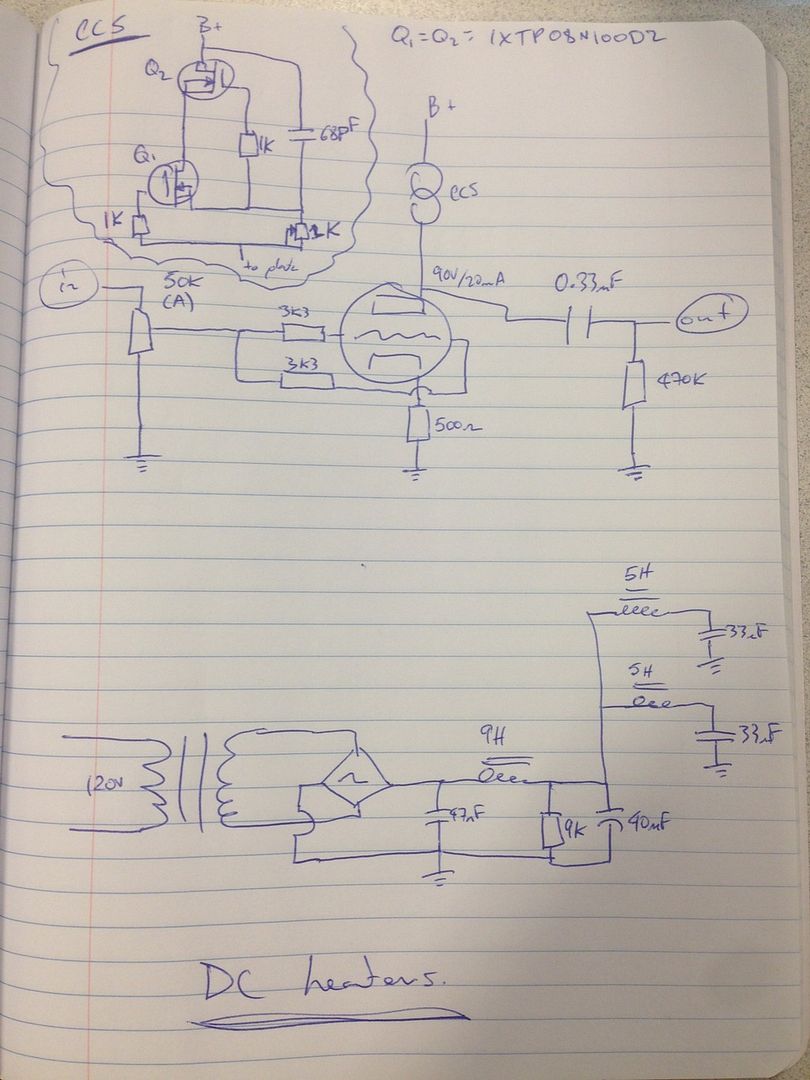
See my proposed schematic below
Questions:
1. What chokes/inductors are people using?
2. What PT secondary voltage are people using? From my calculations the design needs ~140V DC or higher for the B+. It seems a standard 120V AC secondary (or higher) would be good.
3. What do people like for biasing? 90V/20mA is going to be my starting point.
4. My output cap is 0.33uF with a 470K to ground. This creates a rolloff frequency of 1 Hz. Not sure why a 3.3uF and 1.5M are used on the original design.
5. What is the purpose of the 47nF “fudge factor” cap?
Thanks!
4. You need to take into account what it is connected to.
5. Raise the B+ voltage a bit.
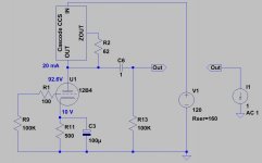
4. My power amp has an input impedance of 68K. With the 470K pulldown resistor (ignoring the output impedance of the 12B4 as it is so low) this makes the equivalent input impedance 59K4. This is still adequate. I see your point though, if my poweramp had an input impedance of 1M it would be a different story.
5. I realize the 47nF cap is a filter cap. Is there anything else I am missing?
5. For a cap input filtering the B+ voltage is the secondary voltage time the square root of 2. For choke input it is 0.9 times the secondary voltage, provided the choke is greater than (B+/Iq)/1130. The small cap allows adjustment between these two values. It is really isn't a filter cap. So, you missed that.
What is "(B+/Iq)/1130" term?5. For a cap input filtering the B+ voltage is the secondary voltage time the square root of 2. For choke input it is 0.9 times the secondary voltage, provided the choke is greater than (B+/Iq)/1130. The small cap allows adjustment between these two values. It is really isn't a filter cap. So, you missed that.
Why would I want to adjust the voltage between 1.414*Vsec and 0.9*Vsec? There is easier ways to drop voltage if need be.
Since the input to the power supply circuit is a cap (a small one) what is the equation to determine what the voltage will be within the 1.414*Vsec and 0.9*Vsec range?
B+ = supply output voltage or 0.9 times the secondary voltage
Ah, to use a transformer that you have? Maybe; but, it won't sound the same.
There isn't one.
Perhaps you'd understand more if you played with PSUD II. You don't have a very good grasp of the basics, yet.
Ah, to use a transformer that you have? Maybe; but, it won't sound the same.
There isn't one.
Perhaps you'd understand more if you played with PSUD II. You don't have a very good grasp of the basics, yet.
The 47 nF. cap. is a "fudge factor" part. The PSU filter is pseudo choke I/P. A pure choke I/P filter yields a rail voltage approx. 0.9X the AC RMS value, less losses. With "120" VRMS out of the power trafo, the rail will be too "short". If the cap. is under 1 muF., critical current behavior and good regulation are maintained. The 47 nF. value is a point of departure. You will have to use cut and try, at the bench, to get the rail close to, but not above 125 VDC.
I'll have some power "iron" recommendations this evening.
I'll have some power "iron" recommendations this evening.
Hi Eli, thanks for the clear response, this is making sense. I will have to tweak the cap myself with my setup when I build it if we are aiming for 125V B+ for the CCS input voltage.The 47 nF. cap. is a "fudge factor" part. The PSU filter is pseudo choke I/P. A pure choke I/P filter yields a rail voltage approx. 0.9X the AC RMS value, less losses. With "120" VRMS out of the power trafo, the rail will be too "short". If the cap. is under 1 muF., critical current behavior and good regulation are maintained. The 47 nF. value is a point of departure. You will have to use cut and try, at the bench, to get the rail close to, but not above 125 VDC.
I'll have some power "iron" recommendations this evening.
My only question remaining is; Why not use a large electrolytic cap like many power supplies do then drop the voltage with a linear device like a resistor to achieve the desired rail voltage?
Looking forward to your "iron" recommendation!
No idea what you are saying here. You did not explain your "(B+/Iq)/1130" statement at all. You have B+ on top measured in volts divided by total current in the bottom measured in amps. This gives you a numeric value in ohms. You then divide again by a random constant you didn't explain of 1130. You are left with some value "X" in ohms divided by 1130. Again no idea what you are saying here.B+ = supply output voltage or 0.9 times the secondary voltage
No idea what you are saying here. I don't have a transformer yet. Maybe this is in regards to my question about dropping the voltage with a linear device and why that is not desirable.Ah, to use a transformer that you have? Maybe; but, it won't sound the same.
Are you trying to communicate there isn't an easier way to design this PSU with the same performance?There isn't one.
I very much beg to differ.You don't have a very good grasp of the basics, yet.
My only question remaining is; Why not use a large electrolytic cap like many power supplies do then drop the voltage with a linear device like a resistor to achieve the desired rail voltage?
Chris,
Cap. I/P filters exhibit poor regulation. OTOH, critical current filters are inherently well regulated. You could use the same power trafo and bridge rectifier I recommend with cap. I/P filtration and a pair (1/channel) of Maida style regulators. 125 VDC is a compromise between decent critical current regulation and having sufficient compliance to operate the CCSes. If you go cap. I/P filter plus active regulation, keep the B+ voltage as "tall" as can be, consistent with not having the regulators drop out. You decide how your money gets spent.
Looking forward to your "iron" recommendation!
I'm going to give Mouser stock numbers, but it may make sense for a Canadian, like you, to order elsewhere.
Triad N-68X (553-N68X) 50 VA isolation trafo, which feeds the B+ PSU
Triad VPL24-1100 (553-VPL24-1100) Dual "12" VAC filament trafo
4X Cree C3D02060F (941-C3D02060F) 600 PIV/2 A. Schottky diodes for bridge rectifier
Hammond 159P (546-159P) 10 H./125 mA. filter choke
2X Hammond 155H (546-155H) 5 H./50 mA. filter chokes
Xicon 286-10K-RC (286-10K-RC ) 10 Kohm/5 W. metal oxide bleeder resistor
All,
The Triad power "iron" suggested has dual primaries, which makes them "universal".
The critical current, in mA., needed for good regulation when (pseudo) choke I/P filtration is employed is approx. V/L. It works out that 1 Kohm of bleeder resistance/henry of I/P inductance ensures that the critical current gets drawn. Please observe that larger inductances require smaller critical currents.
With cathode degeneration and a CCS load this preamp will have quite high output impedance so it will need a short output cable.
A hybrid cap/choke input PSU (i.e. small first cap) is likely to give worse regulation than a cap input or a choke input. I am puzzled why this is so popular.
A hybrid cap/choke input PSU (i.e. small first cap) is likely to give worse regulation than a cap input or a choke input. I am puzzled why this is so popular.
Hi Eli,Chris,
Cap. I/P filters exhibit poor regulation. OTOH, critical current filters are inherently well regulated. You could use the same power trafo and bridge rectifier I recommend with cap. I/P filtration and a pair (1/channel) of Maida style regulators. 125 VDC is a compromise between decent critical current regulation and having sufficient compliance to operate the CCSes. If you go cap. I/P filter plus active regulation, keep the B+ voltage as "tall" as can be, consistent with not having the regulators drop out. You decide how your money gets spent.
The chokes you listed add up to $80. For that amount or less I could build/buy a regulated power supply that would provide better performance could I not?
It seems the benefit of this simple PSU is mitigated by the high cost due to the pricing of the chokes/inductors.
With cathode degeneration and a CCS load this preamp will have quite high output impedance so it will need a short output cable.
Both the mu and the plate resistance of the 12B4 are very low. The effects you describe have little impact, in this specific case.
A hybrid cap/choke input PSU (i.e. small first cap) is likely to give worse regulation than a cap input or a choke input.
Only a small amount of "fudge" can be tolerated. When the I/P cap. is held under 1 muF., critical current behavior is retained. You're correct about it not taking much capacitance to turn things into a poorly performing cap. I/P filter.

Hi Eli,
The chokes you listed add up to $80. For that amount or less I could build/buy a regulated power supply that would provide better performance could I not?
It seems the benefit of this simple PSU is mitigated by the high cost due to the pricing of the chokes/inductors.
As I stated, you decide how your money gets spent. I worked that PSU up to accommodate "Buzz". He already had inductors in his "junk box".
Keep the pseudo dual mono concept intact, for superior channel separation. You need a B+ regulator for each channel. The cost of 2X regulators could easily be lower than the "iron" PSU.
IMO, you will very hard pressed to better Schottky bridge rectifying a Triad N-68X, in obtaining the "raw" B+. The Triad VPL24-1100 for heater power is also (IMO) a "winner".
12B4 has a mu around 6. A cathode resistor of 500R should give anode impedance around 4k. This is a bit high for a preamp output, but OK if short cables are used.
Thanks for the historical information on why the PSU was chosen.As I stated, you decide how your money gets spent. I worked that PSU up to accommodate "Buzz". He already had inductors in his "junk box".
Keep the pseudo dual mono concept intact, for superior channel separation. You need a B+ regulator for each channel. The cost of 2X regulators could easily be lower than the "iron" PSU.
IMO, you will very hard pressed to better Schottky bridge rectifying a Triad N-68X, in obtaining the "raw" B+. The Triad VPL24-1100 for heater power is also (IMO) a "winner".
If going the regulator route why is two separate regulator circuits recommended?
Since Rk is unbypassed Zo = Ra || (ra + Rk + μRk)12B4 has a mu around 6. A cathode resistor of 500R should give anode impedance around 4k. This is a bit high for a preamp output, but OK if short cables are used.
ra = 4K like you said, but what does Ra equal since Ra is the CCS?
With cathode degeneration and a CCS load this preamp will have quite high output impedance
Are you going to get degeneration with a CCS? With a good CCS I believe you won't. The CCS will force a constant voltage across the cathode R. In fact I don't believe you'll see any change if you bypass that resistor or replace it with LED bias.
The cathode resistor will not reduce gain with a CCS anode load, but it will still increase output impedance.
Ra is infinity (in theory) so Zo = ra + Rk + μRk i.e. 4k. If you want the cable alone to have an HF cutoff above 50kHz then you need cable capacitance plus amp input capacitance to be below around 750pF. Allow 250pF for the amp, then the cable must be less than 500pF. This could be 5m at 100pF/m. OK, not too serious a problem but it does assume that all capacitances are linear so HF rolloff is the only issue.ChrisM91 said:Since Rk is unbypassed Zo = Ra || (ra + Rk + μRk)
ra = 4K like you said, but what does Ra equal since Ra is the CCS?
Isn't another issue that 4K is simple a high output impedance and will cause loses?The cathode resistor will not reduce gain with a CCS anode load, but it will still increase output impedance.
Ra is infinity (in theory) so Zo = ra + Rk + μRk i.e. 4k. If you want the cable alone to have an HF cutoff above 50kHz then you need cable capacitance plus amp input capacitance to be below around 750pF. Allow 250pF for the amp, then the cable must be less than 500pF. This could be 5m at 100pF/m. OK, not too serious a problem but it does assume that all capacitances are linear so HF rolloff is the only issue.
My poweramp has an input impedance of 68K. The 4K output impedance in conjunction with the 68K input impedance will cause a signal attenuation of 5.5%.
- Status
- Not open for further replies.
- Home
- Amplifiers
- Tubes / Valves
- 12B4 Preamp – Design/Pre-build Questions