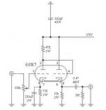
Please refer to post #17 for the schematic.
Can I use an electrolytic capacitor for the 1uF capacitor on the output of this preamp? I know, someone will say "yuck" for using an electrolytic in this position, but I only ask because I want to bread board this circuit, and all I have are electrolytics.
Is polarity important if I decide to use them?
I will use a "Kimber Kap" if this works ok.
Thank you.
Glenn
Thank you for that interesting reading.
I really like the tubes with the 2 grid caps! Very unique.
I'm glad to hear you like the oil filled motor run caps as I'm building a KT88 SET power amp using those. I'm not finished yet, so I'll have to let you know how it sounds later.
I still need an answer to the electro cap useage for the output line. I've never seen them used in this position, but I don't think it should be a problem. I also don't think the polarity matters, but I'm still relatively new at this.
Thanks.
Glenn
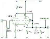
Yes, you can use an electrolytic and yes the polarity will matter. Positive end toward the cathode.
Thanks Sy!
I see now that the schematic does show the + towards the cathode. It will probably sound like CR_P, but I do have them on hand. It's just for a bench top test anyway.
Glenn
I see now that the schematic does show the + towards the cathode. It will probably sound like CR_P, but I do have them on hand. It's just for a bench top test anyway.
Glenn
Yes, the cathode follower has a much more sensible load and biasing. However, you'll want to put a protection diode between the grid and cathode to allow the tube to survive turn-on and turn-ff.
SY said:Yes, the cathode follower has a much more sensible load and biasing. However, you'll want to put a protection diode between the grid and cathode to allow the tube to survive turn-on and turn-ff.
What is the issue with turn-on/turn-off? Is it a cold heater issue? I'm using a 5Y3GT rectifier with this circuit.
Diode between the screen and cathode of which half of the tube (pins#4&6)? Which direction is the diode installed? Cathode of the diode to cathode of the tube, or the other way around? 1n4007's (solid state!!) ok?
Maybe you could explain why a diode is needed for turn-on/off protection, I'm still learning 🙂
Thanks Sy!
"Yes, the cathode follower has a much more sensible load and biasing."
Hi Sy,
Why do you think 18k is a better load for a 6SN7 than 47k?
Hi Sy,
Why do you think 18k is a better load for a 6SN7 than 47k?
Here's another couple of questions on this circuit. What is the 1Meg resistor tied to ground right before the output for?
What happens if the output capacitor fails and you have your headphones plugged into the amp? 😱
Glenn
What happens if the output capacitor fails and you have your headphones plugged into the amp? 😱
Glenn
1. To stop a lout pop when the headphones are connected, or a shock if you touch.porkchop61 said:Here's another couple of questions on this circuit. What is the 1Meg resistor tied to ground right before the output for?
What happens if the output capacitor fails and you have your headphones plugged into the amp? 😱
Glenn
2. It won't if you adequately rate it. It's not life threatening so adequate rating is sufficient.
Re: "Yes, the cathode follower has a much more sensible load and biasing."
Current. 6SN7 likes current. The 5.6mA number on the schematic doesn't make sense to me; looking at the tube curves, it looks more like 2 or 3 mA.
Porkchop, the diode is connected between cathode and grid, reverse-biased in normal operation (i.e., arrow pointing to the grid). Remember, when the first section is drawing no current (e.g., during warmup), the grid will see the full B+ on it while the cathode is still at ground. The diode clamps the grid and cathode to prevent such an overvoltage situation.
Joel said:Hi Sy,
Why do you think 18k is a better load for a 6SN7 than 47k?
Current. 6SN7 likes current. The 5.6mA number on the schematic doesn't make sense to me; looking at the tube curves, it looks more like 2 or 3 mA.
Porkchop, the diode is connected between cathode and grid, reverse-biased in normal operation (i.e., arrow pointing to the grid). Remember, when the first section is drawing no current (e.g., during warmup), the grid will see the full B+ on it while the cathode is still at ground. The diode clamps the grid and cathode to prevent such an overvoltage situation.
"Current. 6SN7 likes current. The 5.6mA number on the schematic doesn't make sense to me; looking at the tube curves, it looks more like 2 or 3 mA."
2.8mA per triode, 5.6mA total. As I said before, Porkchop61 has modified a drawing of mine of the single 6SN7 stage into an amp of his own design. The labels got moved around in the process, a second 6SN7 channel got added, and a PSU.
RE: 6SN7 and current
Linearity is affected by op point and load. 18k is a poor load for a 6SN7, regardless of the Ib. If you want to run the standard 9mA, 250V point, then switching to a choke cathode load like the Lundahl LL1667/15mA is a fine choice.
But even with a choke, or the world's greatest CCS, at the end of the day you're still going to be loading the 6SN7 with whatever you hook up to this thing, and not truly the choke/CCS/resistor.
Joel
Well, that's point- the AC load will be something more like 10K. The current swing to get 2.5VRMS across 10K is 0.25mA (or more than a third of a milliamp peak). That certainly suggests that a high idle current would be more desirable so that the signal current is a much smaller percentage of the idle current.
The rp and mu level out quite a bit when you run higher currents (more than 5-7mA).
The rp and mu level out quite a bit when you run higher currents (more than 5-7mA).
Re: Re: "Yes, the cathode follower has a much more sensible load and biasing."
Yes, I thought this might be the case. I use this resistor on all my guitar pedal builds as a pulldown resistor for the same reason.
Ok, good to know I won't get toasted if the capacitor fails 😱
Thank for that explanation Sy, makes sense to me.
Time to add those 1N4007's to the schematic 🙂
Glenn
dhaen said:
1. To stop a lout pop when the headphones are connected, or a shock if you touch.
2. It won't if you adequately rate it. It's not life threatening so adequate rating is sufficient.
Yes, I thought this might be the case. I use this resistor on all my guitar pedal builds as a pulldown resistor for the same reason.
Ok, good to know I won't get toasted if the capacitor fails 😱
SY said:
Porkchop, the diode is connected between cathode and grid, reverse-biased in normal operation (i.e., arrow pointing to the grid). Remember, when the first section is drawing no current (e.g., during warmup), the grid will see the full B+ on it while the cathode is still at ground. The diode clamps the grid and cathode to prevent such an overvoltage situation.
Thank for that explanation Sy, makes sense to me.
Time to add those 1N4007's to the schematic 🙂
Glenn
Sy-
With regards to the diode you suggested.
What did they do 50 years ago? They didn't have soild state diodes
Just curious.
Glenn
With regards to the diode you suggested.
What did they do 50 years ago? They didn't have soild state diodes
Just curious.
Glenn
They often used neon bulbs. You'll see them a lot in old tube opamps and in amps with direct coupling like the Marantz 9.
Ahh, yes I have seen neon lamps in old guitar amplifier circuits.
Very creative use of a neon lamp.
Thanks.
Glenn
Very creative use of a neon lamp.
Thanks.
Glenn
- Status
- Not open for further replies.
- Home
- Amplifiers
- Tubes / Valves
- 12AY7/6SN7 preamp PSU check