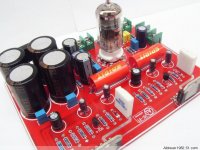
Hi. Just got my amp from eBay and theres no schematic included. Ive mailed the seller repetedly but to no avail. Can any of u fellas help? Planning to mod the feedback loop and too Im thick to find it the right resistors? Need a schematic?
The logo on the board says: Ai HI-FI, aibiwen
Regards /Bo
The logo on the board says: Ai HI-FI, aibiwen
Regards /Bo
Attachments
Just draw the circuit from looking at the board. Take a sheet of paper, a pencil and an eraser, draw the chips and the tube first, and then fill in the blanks. The capacitors usually have their value written on them in plain text, the resistors as a color code: 5 Band Resistor Color Codes.
For chips' and tube's pinout see:
http://www.national.com/ds/LM/LM3886.pdf
12AX7 - Wikipedia, the free encyclopedia
And please post your schematic, I'm sure there are more than a few people interested. 🙂
For chips' and tube's pinout see:
http://www.national.com/ds/LM/LM3886.pdf
12AX7 - Wikipedia, the free encyclopedia
And please post your schematic, I'm sure there are more than a few people interested. 🙂
If you need help identifying parts just take a picture and post it here, we'll help. While we're at it, e few more pictures would be nice anyway😀
This might help: 12AX7µç×Ó¹ÜÇ°¼¶+LM3886ºó¼¶¹¦·Å
Hahaha... thats it 😀 No info on the LM3886s feedback loop though. But I found this:
An externally hosted image should be here but it was not working when we last tested it.
Theres 0.2ohm 2w resistors on my output as well
Regards /Bo
If you need help identifying parts just take a picture and post it here, we'll help. While we're at it, e few more pictures would be nice anyway😀
Took these. Hope it helps. Need any other angles just let me know 🙂
Regards /Bo


The circuit of your actual amp must be different from the one you found. The feedback resistors will be close to the output, I'm guessing 22k and 1k. Look here: http://img03.taobaocdn.com/bao/uploaded/i3/T13NFyXkNoXXawiOU8_101122.jpg. Just reverse-engineer the circuit, you'll learn a lot.
What type are the small transistors?
What type are the small transistors?
Hi,
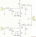
check if your circuit matches the posted schematic.
The posted schematic has problems.
Does your circuit work properly?
The feedback of the inverting chipamps is 200k & 10k.
The input bias currents flow through the 10k into each other. This will upset the input offset voltages and the output offset voltages.
The three 10k are in parallel to the 47k giving an input impedance of ~3k11
The gain is 20times (+26dB)
Your source must be able to drive that 3k11.
A valve at the input used as a buffer to drive that 3k11 is in the wrong place. The buffer should be back at the output of the source.
Last edited:
Rodeodave: Upon further inspection ur right. Theyre different. Ive mailed hifibar.net regarding the schematic. The amp was bought off some dude on eBay. If theres no reply from them I'll reverse engineer it.
That PCB-board looks spot on. Any further info on it? The transistors says: S9014, C331
AndrewT: Amp is not up and running yet. Still need to order transformer and some other stuff. Still gathering info on what is need to complete the amp.
Speaking of that. Im thinking a 24-0-24 3.33A transformer? Any thoughts on that?
btw: Ive never built a power amp before.
Regards /Bo
Hi,
No, no further info. I just googled for "12AX7 LM3886" and switched to image search.
Regarding the amp-building...Read a lot of articles here: DIY Audio Articles (especially the Power Supply section) and here: DIY Audio Projects - Hi-Fi Blog for Audiophiles. A lot of info on gainclones can be found here: Gainclone chip amp index page.
Hi,
No, no further info. I just googled for "12AX7 LM3886" and switched to image search.
Regarding the amp-building...Read a lot of articles here: DIY Audio Articles (especially the Power Supply section) and here: DIY Audio Projects - Hi-Fi Blog for Audiophiles. A lot of info on gainclones can be found here: Gainclone chip amp index page.
Excellent links. Many, many thanks 🙂
Hi. Just got my amp from eBay and theres no schematic included. Ive mailed the seller repetedly but to no avail. Can any of u fellas help? Planning to mod the feedback loop and too Im thick to find it the right resistors? Need a schematic?
The logo on the board says: Ai HI-FI, aibiwen
Regards /Bo
Hello all!
Since i am very interested in this hybrid amplifier with ECC83 (12AX7) + LM3886, because if someone is able to some accounts schematics.
Thank you!
Hey Bo,
Sorry to disappoint you, but the tube buffer is really bad engineered and will as is give high distortion. It might be possible to make something out of it though. Probably
best to bypass the tubestage as as long as it is in it´s present form.
Why do you want to modify the feedback loop?
AndrewT talked about buffer and that is where a tube could be used when runnning in inverted mode, but then connected as a CF.
Hey Bo,
Sorry to disappoint you, but the tube buffer is really bad engineered and will as is give high distortion. It might be possible to make something out of it though. Probably best to bypass the tubestage as as long as it is in it´s present form.
Why do you want to modify the feedback loop?
AndrewT talked about buffer and that is where a tube could be used when runnning in inverted mode, but then connected as a CF.
My experience with the 12AX7 is that its high output impedance will make driving "through" that capacitor difficult. A 12AT7 is almost drop-in replacements here and would work better. A 12AU7 or 6DJ8/6922/ECC88/6N23P would be more ideal but would require some parts value changes.
I tried to attach the original 12AX7 schematic for the front end from the web site.
Attachments
Last edited:
Sorry to say but the AT and AU are equally sh-tty at these B+ voltages. It is equally sh-tty to use a voltage amp here. A CF could be used with the GC in iverted mode but is unnecesary. Most source can cope with the normal GC Zin of 10k.
Rev is repeating the general advice that many choose to ignore.
The chipamp range from most manufacturers do not need a buffer, nor a gain stage at their inputs.
The big exceptions are if you require an inverting version of the chipamp. Most Sources cannot properly drive an inverting chipamp. That is a Source fault not the chipamps.
There are two solutions:
Convert the inverting chipamp impedance to one that can be driven by inadequate Sources by adding a buffer to the chipamp input.
or
Add a buffer to the output of the Source, such that it can drive a low Zin inverting chipamp.
And there is one other situation that requires input modification. A balanced to unbalanced input to drive the chipamp from very long cables in a high interference environment.
I imagine that the Tube buffer here is not for impedance matching, more for "Euphonic distortion" so the high distortion is probably intentional. If this approach to sound repoduction is right or not is more of a philisophical discussion.
The other designs on the site seem to use the buffer on a non inverting design so the input impedance of the amp should not be an issue. (However I haven't reverse engineered this one so it may be different)
The layout of the amp itself does not look optimum for the lowest distortion into 4ohm (or lower loads) at high currents the local decoupling caps needed to be as close as possible to the chip. The track length shown here cause problems in the design I worked on, we had to move the 22uF decoupler to be next to the chip.
However the design did not actually go unstable under normal conditions it was only under full load testing that we found the problem. So it will probably work OK just not be quite optimum on large transients.
Regards,
Andrew
Sorry to say but the AT and AU are equally sh-tty at these B+ voltages.
I wouldn't use any of those tubes w/less than 75-100 volts on the plate. And the 12AX/T/U7's: I would likely connect both sections in parallel in each tube for extra drive, lower noise, and all that good stuff. Actually, I'd love a 6SN7 or 6SL7 there... 😀
It is equally sh-tty to use a voltage amp here.
Well, Mauro Penasa is getting some mileage and a devoted following out of doing just that. Although it's an LM318 chip for voltage gain driving an LM3886 as a current amp. Or something like that; I'm sure I haven't described it completely.
A CF could be used with the GC in iverted mode but is unnecesary. Most source can cope with the normal GC Zin of 10k.
I don't understand all your abbreviations - CF, GC, etc. Please spell out abbreviations at least once in a message so the rest of us can follow your argument. (By "argument" I mean in the logic, debate, or educational sense, not the "arm waving/shouting" sense)
Thanks for the reply. 🙂
I imagine that the Tube buffer here is not for impedance matching, more for "Euphonic distortion" so the high distortion is probably intentional. If this approach to sound repoduction is right or not is more of a philisophical discussion.
My thoughts exactly, given the apparent design. Although the argument can be made for pairing tubes as voltage amplifiers (where the truly excel) with transistors (or MOSFETs) as current amplifiers (where THEY truly excel). The Aikido Hybrid is one such project that's got a thread or two devoted to it. I've never built or heard one, so I can't opine as to the success of the approach - it just seems to have some theoretical merit.
The layout of the amp itself does not look optimum for the lowest distortion into 4ohm (or lower loads) at high currents the local decoupling caps needed to be as close as possible to the chip. The track length shown here cause problems in the design I worked on, we had to move the 22uF decoupler to be next to the chip.
It would have helped if the 3886 designer had put the V+/V- connections at opposite ends of the chip so that we could hang some useful capacitance within 10mm or so.
The pinout of the LM3886 is well designed. Point is i) to minimize the enclosed loop areas between V+ and OUT, and V- and OUT resp. and ii) to keep these high-current and high-frequency loops (half-wave rectification!) away from the input circuitry.
A few centimeters of distance to the decoupling caps is not much of problem if inductance is very low, this can be achieved by wide traces and minimized loop area. With double sided PCB it is not that hard... (but many of the far-east chipamp products are not very well routed, obviously).
A few centimeters of distance to the decoupling caps is not much of problem if inductance is very low, this can be achieved by wide traces and minimized loop area. With double sided PCB it is not that hard... (but many of the far-east chipamp products are not very well routed, obviously).
Last edited:
- Status
- Not open for further replies.
- Home
- Amplifiers
- Chip Amps
- 12AX7 + LM3886 schematic