Hello
I am wondering if there is a commercial tube tester that specifically test for gain of 12AX7 tubes
I guess not all 12AX7 tubes are equal, and some has more gain than others, not sure if this is true.
Does it makes sense to build a test rig with a simple amplifier circuit ? or will all test equal ?
thanks in advance for your opinion
regards
Alexander
Why care ? Tubes differ, maybe +-20% but an amp that depends on a specific value
of gain ( or Gm or Ra ) is broken by design.
of gain ( or Gm or Ra ) is broken by design.
The Valve Wizard
I can use it to determine the Mu of tube model, real triode or pentode strapped triode when in doubt. Together with Gm mode, it should a very handy tool to own without having spend much money.
I can use it to determine the Mu of tube model, real triode or pentode strapped triode when in doubt. Together with Gm mode, it should a very handy tool to own without having spend much money.
Attachments
Tubes do not have "gain"; circuits have gain. Tubes have amplification factor and transconductance. Which parameter are you interested in?
Why care ? Tubes differ, maybe +-20% but an amp that depends on a specific value
of gain ( or Gm or Ra ) is broken by design.
So all phono stages that don't use feedback are flawed by design?
I am wondering if there is a commercial tube tester that specifically test for gain of 12AX7 tubes.
You want a tester that can measure transconductance. The application circuit
produces the voltage gain.
this tube has much internal resistance.Hello
I am wondering if there is a commercial tube tester that specifically test for gain of 12AX7 tubes
I guess not all 12AX7 tubes are equal, and some has more gain than others, not sure if this is true.
Does it makes sense to build a test rig with a simple amplifier circuit ? or will all test equal ?
thanks in advance for your opinion
regards
Alexander
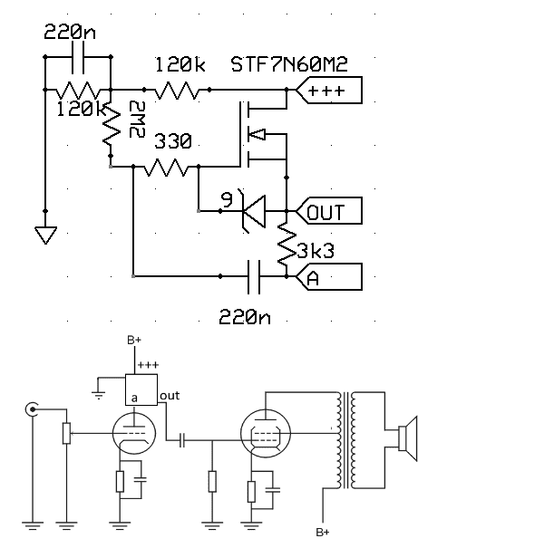
that means, even biggest possible Ra and next stage Rg will significantly drop the gain.
also the miller capacitance of big tubes loads the 12ax7 at treble..
to maximize gain&minimize distortion, you must put this tube under mosfet gyrator. it sounds much better.
Last edited:
Depends on your expectations. If you want it to follow riaa curve you mustSo all phono stages that don't use feedback are flawed by design?
have a design that is not depending on tube parameters.
Same with the output level, here a simple adjustment pot could be used.
A good design ( imho) would accept any valid ECC83 and still work within
narrow limits.
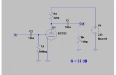
With the below circuit you can sort 12AX7 tubes by gain.
Will that work without a cathode resistor ?
Will that work without a cathode resistor ?
The bias is Vgs = 0V, so not much input acceptance.
Did you notice the value of grid resistor ?Will that work without a cathode resistor ?
It is 10 Meg. This is typical grid leak bias. The grid voltage settles to about 0.8 V.
This kind of circuit works well with small signal levels.
Did you notice the value of grid resistor ?
It is 10 Meg. This is typical grid leak bias. The grid voltage settles to about 0.8 V.
This kind of circuit works well with small signal levels.
I did but it seems like an unusual way to test a valve.
I would have used a bypassed cathode resistor and 1m grid resistor.
Then apply a sine wave and monitor output at anode.
Unusual ?
What particular problem exist with it, taking into account the original purpose that was described .
Cathode bias is negative feedback for DC, which means that it essentially "hide" some difference between the tubes under test.
What particular problem exist with it, taking into account the original purpose that was described .
I would have used a bypassed cathode resistor and 1m grid resistor.
Cathode bias is negative feedback for DC, which means that it essentially "hide" some difference between the tubes under test.
Unusual ?
What particular problem exist with it, taking into account the original purpose that was described .
Cathode bias is negative feedback for DC, which means that it essentially "hide" some difference between the tubes under test.
I would want to test a valve in a typical application circuit not some way out odd circuit.
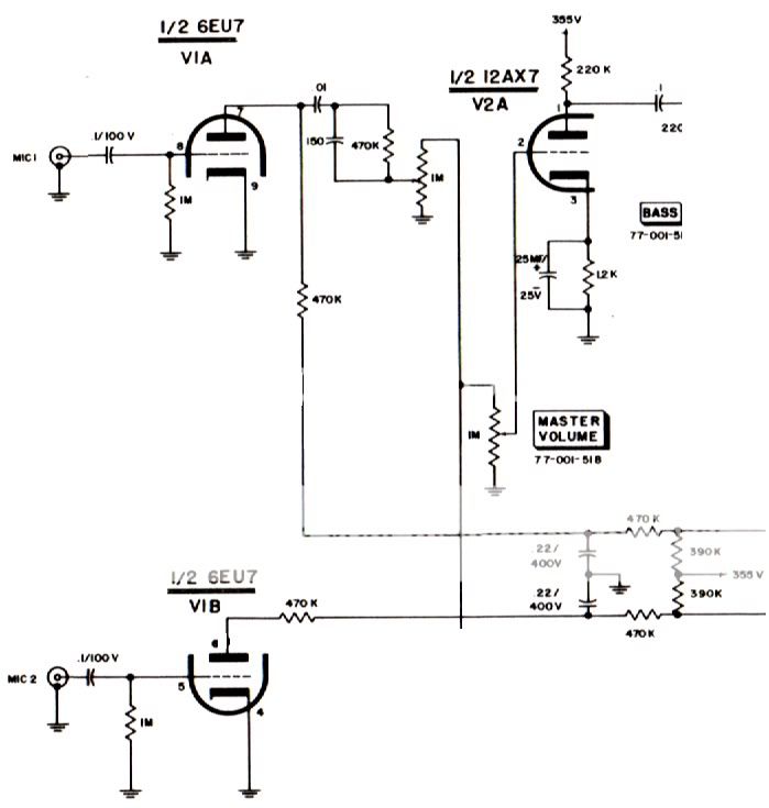
Technical explanation: (Quote from: http://www.angelfire.com/planet/funwithtransistors/Book_CHAP-4A.html )
An amplifier stage in which the cathode is grounded and there is no external source of bias is called a zero bias amplifier. The bias isn't really zero because the action of the tube will develop a small amount of bias. This is sometimes called contact bias because it is generated by electrons coming in contact with the grid.
The grid wires are thin and very few electrons strike them but there are billions of them passing by so even a small percentage is still a very large number. Electrons that strike the grid stick to it and give it a negative charge. If the grid resistor is made very large, say 10 meg ohms, the voltage on the grid will be almost a volt. Now, if the tube has been designed so this voltage is the optimum grid voltage, and some have been, the parts count of the amplifier stage can be reduced by two...This circuit is most commonly used in All American 5 radios but is also seen in guitar amplifiers and hi-fi equipment...
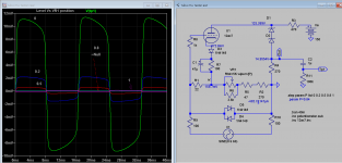
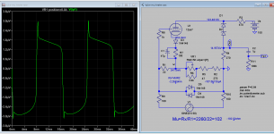
Testing ECC83 should, as a starting point, be done with a circuit similar to
the phillips datasheet.
See page 3 of "https://frank.pocnet.net/sheets/030/e/ECC83.pdf"
Using grid current only is a very uncertain bias source and might result in different bias
depending on tube, humidity, phase of the moon etc.
the phillips datasheet.
See page 3 of "https://frank.pocnet.net/sheets/030/e/ECC83.pdf"
Using grid current only is a very uncertain bias source and might result in different bias
depending on tube, humidity, phase of the moon etc.
"test for gain" is not a complete test description.
Most of the many things sold as 12AX7 will have raw gain +/-20%. It is hard for gain to be higher. If gain is less, some customers may complain.
When used In-Circuit, the fixed resistors against the tube variation tend to reduce gain variation. For 12AX7 (very responsive to resistor loading) the actual variation of gain will be more like 10%.
10% is 1dB. Yes, you want left/right matched better than 1dB. However in an amplifier *chain* you may have 20dB even 60dB of gain. What do you want? More gain? Less gain? Either way, if gain is not just-right then 1dB is not a significant change in gain.
There's also a thing "NFB" which was *developed* to make very long hundreds-of-tubes telephone lines stable to within a few dB despite tube variation and 1000-hour aging. Naked 12AX7 have use for guitar-amp color but I'd rarely want a naked no-NFB 12AX7 in a hi-fi. (Last one I had, I tore it out.)
- Status
- Not open for further replies.
- Home
- Amplifiers
- Tubes / Valves
- 12AX7 gain test