Merry Christmas - here is a preliminary schematic and layout of a proposed partial feedback HP amp using the cheap and abundant 12AQ5 with soild state front end. This would run off a 24V switching wall adapter with HV provided by a DC-DC converter of my own design. The solid state cathode bias may make the circuit too slippery to handle, so I reserve the option to revert to resistive cathode bias with partial bypassing. Values currently are placeholders, and compensation is definitely up in the air until I pair the design with some output iron. I'll start with ~5mA bias for the front end mosfet.
Oh, yeah, and I won't be sending out for any boards until I figure out how to bodge in the protection diodes for the front end mosfet. Adding a small negative bias to the anodes of the protection zeners to reduce capacitance may be an option. Consider the design a breadboard at this point.
Oh, yeah, and I won't be sending out for any boards until I figure out how to bodge in the protection diodes for the front end mosfet. Adding a small negative bias to the anodes of the protection zeners to reduce capacitance may be an option. Consider the design a breadboard at this point.
Attachments

But all feedback is partial. The wanted signal has to get in there too! Your circuit uses standard global negative feedback plus local negative feedback round the 12AQ5 to linearize it.
You are lacking supply RC filtering between the output tube and the driver FET - that's a feedback path you do not want, just using decoupling caps may not be enough. The supply current needs to come in at the output tube end of the rail ideally.
You are lacking supply RC filtering between the output tube and the driver FET - that's a feedback path you do not want, just using decoupling caps may not be enough. The supply current needs to come in at the output tube end of the rail ideally.
I've left many options open in this design. Not all of them need necessarily be tried at the same time. The main feature to try is the inner feedback loop to emulate triode characteristics in the output pentode. I may opt to first run without the global loop, concentrating all my feedback in the inner loop.
I'm keeping the option for a global loop in order to possibly prop up the low end response. The transformers I'm trying first (since I have them in hand) are the Transcendar TT-106-OT, with only 20H primary inductance. I've had reasonably good luck getting decent gain-phase response with this transformer in a previous triode design. Unfortnately, I didn't run any scans on that design without the global loop. I may try dragging the finished project back in to work to see what difference the global loop makes in the frequency response.
Your comments re filtering between the output and input stages are interesting. It's not too much trouble to shove some things around in the layout to make that possible. Thanks for chiming in before I sent out for boards...
I have access to a good gain-phase analyzer at my workplace, so many sins of both omission and commission are revealed in detail.. Scans with and without the filtering might prove interesting.
Just put in the order from PCBway for some boards to build this thing. I'll be documenting how it morphs along the way.
Boards are in hand as of today - I will be assembling this project in the next couple of weeks, probably using Transcendar iron for starters.
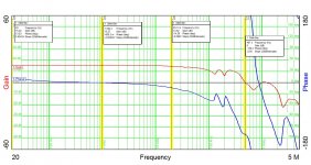
I presume that droop in frequency response at HF is mainly due to the gate capacitance of the input MOSFET. It seems to be ~2dB or so down by 20kHz, although its hard to see with the 10dB/div scale.
I tried to look up the MOSFET datasheet but I think you've got the part number wrong, I can't find ITP01N100D or even IRP01N100D
I tried to look up the MOSFET datasheet but I think you've got the part number wrong, I can't find ITP01N100D or even IRP01N100D
I'd more likely blame the HF droop on the characteristics of the transformer. A little more research will tell. The overall response looks a lot better than I expected.
I almost went with a design using a cascoded jfet at the input, but opted instead for the depletion mod mosfet for a lower parts count. The mosfat in question (IXTP01N100D) only has 120pF of input capacitance. Feedback is pretty severe, so the effect of the mosfet Miller capacitance may not be as much as one might think.
I was thinking of rolling off the HF response to get rid of the HF bumps, but they may not matter all that much. I'll see what the square wave response looks like.
Last edited:
BTW, the amplitude and phase are shown clearly in the plot, with markers placed at 20Hz, 1kHz, 20kHz, and at the amplitude 0dB crossover. The amplitude is down 0.75 dB at 20 kHz, and 0.05dB at 20Hz.
Last edited:
In my opinion, the circuit looks too complex for a simple task. With ½w, a headphone is more than excited, and a 12AQ5 is capable of 3-4W in usual usage. For decades, 6AQ5 and the like was the output stage at TV and radio sets, with a simple trafo and a 6AV6/6AT6 driving it. But (again) is my opinion, and keep us posted about progress in the amp.
Good luck.
Good luck.
On another note, I may switch tubes from the 12AQ5 to the 5AQ5, as the 5AQ5 has a controlled warm-up filament compatible with series string duty, and the 12AQ5 was really designed for mobile radios in vehicles, and doesn't have controlled warm-up characteristics.. I currently appear to be getting away with using two 12AQ5 filaments in series, but I can't necessarily count on that. Two 5AQ5s in series with an additional 3R9 resistor should work fine with a 12V supply. The 5AQ5 is still a cheap tube.
Last edited:
Osvaldo,
People are doing crazy stuff like using a 2A3 for headphone duty, so I consider this effort somewhat modest in comparison, and much cheaper to boot. If I can find a smaller tube with similar transconductance and good availability, I may try that as well.
People are doing crazy stuff like using a 2A3 for headphone duty, so I consider this effort somewhat modest in comparison, and much cheaper to boot. If I can find a smaller tube with similar transconductance and good availability, I may try that as well.
Osvaldo's comments spurred me to find an even cheaper, lower power tube than the 12AQ5 that should work nicely in this application.
2A3 for a headphone driver‼. A good way to become deaf.
Why not to try some of the old 1.5 or 3V heater small tubes?. Several of the has been designed for hearing aid, and they are cheap too. I have two pentodes of this kind with which I think to make a portable regenerative receiver for AM stations.
Again, only my opinion.
Why not to try some of the old 1.5 or 3V heater small tubes?. Several of the has been designed for hearing aid, and they are cheap too. I have two pentodes of this kind with which I think to make a portable regenerative receiver for AM stations.
Again, only my opinion.
Well, I'm not driving a hearing aid, instead a pair of cans that can be anywhere from 16 ohms to 600 ohms impedance, though my sweet spot is 30-50 ohms. Most of the headphone I've seen have a max power of about 200mW. You can do the math to get the required peak voltages and currents. I also like a little headroom...
A few of the Russian submini power pentodes are in my range of interest. Even those are a bit crazy, as they draw scads more filament power than will ever be delivered to the load, as does any tube I've considered using so far. I have loads of solid state designs that are better suited for the task - this is an exercise in eccentricity.
A few of the Russian submini power pentodes are in my range of interest. Even those are a bit crazy, as they draw scads more filament power than will ever be delivered to the load, as does any tube I've considered using so far. I have loads of solid state designs that are better suited for the task - this is an exercise in eccentricity.
I understand you eccentricity because i am also an eccentric. I am engineering a 22 compactron tube amp DC coupled for only 10WRMS, and is performing well. Lots of heat from those 22 gentlemen. But why not also try, for example, a humble 6FM7 or 6DE7 cheap sweep tube with two triodes inside? They are intended for vertical deflection and are quite linear.
I've already done that in another thread - sounds nice... The tube used there was a 13DR7, and I ran the amp from a 12V switching wall-wart with a custom DC-DC converter to supply the HV.
Last edited:
OK. Please, don't believe that I am trying to neglect you project, perhaps it is a good idea, but I am trying to give you more ideas. My opinions only.
- Home
- Amplifiers
- Headphone Systems
- 12AQ5 Partial Feedback HP Amp