will soon be posting schematic and my simulation results
promising 🙂
and should sure be very good sounding
as lots of neegative global feedback
is very well known to ruin good musical sound
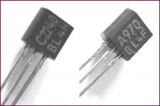
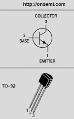
Transistors used
120 Volt 2SC2240 & 2SA970, from Toshiba
http://www.toshiba.com/taec/components2/Datasheet_Sync//50/6461.pdf
http://www.toshiba.com/taec/components2/Datasheet_Sync//50/6451.pdf
and 2N5551 + 2N5401, from OnSemi
http://www.onsemi.com/pub_link/Collateral/2N5550-D.PDF
http://www.onsemi.com/pub_link/Collateral/2N5401-D.PDF
promising 🙂
and should sure be very good sounding
as lots of neegative global feedback
is very well known to ruin good musical sound
Transistors used
120 Volt 2SC2240 & 2SA970, from Toshiba
http://www.toshiba.com/taec/components2/Datasheet_Sync//50/6461.pdf
http://www.toshiba.com/taec/components2/Datasheet_Sync//50/6451.pdf
and 2N5551 + 2N5401, from OnSemi
http://www.onsemi.com/pub_link/Collateral/2N5550-D.PDF
http://www.onsemi.com/pub_link/Collateral/2N5401-D.PDF
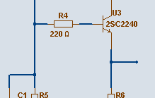
120 Volt preamp
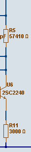
below you can see the input stage
is one pair of 2SC2240
they each work at 1.0 mA
details:
- 220 Ohm base stopper resistors
these 'protect' the input from acting as antennas
should be placed very close to transistor BASE
- 10 pF capacitor at the input transistor
will increase stabilty of the amplifer
by let input 2SC2240 get negative feedback from its own collector
at higher frequencies
- each emitter resistor is at 3000 Ohm
together this makes one 1500 Ohm resistor to feed the pair
the voltage at the transistor emitters is
(1 mA + 1 mA) x 1500 Ohm = 3 Volt
Attachments

Any questions, so far?
From normal www.diyaudio.com Members or or Guests.
-------------------------------------------------------------------------------
I would like very much to all besserwissers (E.E. or Amateur)
to stay away from here.
Thanks. Very kind of you.
I could make one list which ones these are at our forum.
it is a pretty long list, I'm afraid, people.
😉
As well as I could easily make a list with those
that see themselves as Audio Gurus. True or not.
This list is a bit shorter with all well known names.
😉
But it wouldn't be very polite and nice of me to publish such lists.
I leave it up to you & your self mind
to decide if you are welcome in this topic.
Hope you respect to stay away, if you should.
Lineup
6mW of dissipation in the paralleled emitter resistors (tail).
Why do you need a parallel pair 3k0 when most would use a single 1k5?
Is my enquiry welcome or am I on either of your lists?
Why do you need a parallel pair 3k0 when most would use a single 1k5?
Is my enquiry welcome or am I on either of your lists?
Just for information, Perreaux (from New Zealand) used a similar approach in some of their pre-amp designs in the 1980s - these had a fairly high voltage rail which gave them enormous overload margins, and hence fairly low distortion at normal levels.
the voltage at the transistor emitters is
(1 mA + 1 mA) x 1500 Ohm = 3 Volt [/B]
.....Wow...!

120 Volt Pre Amplifier
with
- no global feeedback or
- very low global feedback
Output:
one NPN transistor follower 2SC2240 .. for first version
Now, I maybe will use 2N5551 here (for more power output)
or even, several 2N5551 in parallel Class A
for high output power (read: lower load impedances)
Notice:
1. This output follower is OUTSIDE the voltage feedback loop
to the input pair of 2SC2240 differential stage
2. There is the possibility to break Global Negative FB loop completely.
In this case, the THD distortion actually gets lower.
right now my prtotype shows these figures:
Okay, even if the THD goes up ( especially 2nd ) with feedback
the rest of the harmonics are considerably lower,
than Without Feedback.
The mixture of distortion changes when using feedbac vs. not using feedback.
3. Also for the output follower I use BASE STOPPER resistor, with value 220 Ohm
with
- no global feeedback or
- very low global feedback
Output:
one NPN transistor follower 2SC2240 .. for first version
Now, I maybe will use 2N5551 here (for more power output)
or even, several 2N5551 in parallel Class A
for high output power (read: lower load impedances)
Notice:
1. This output follower is OUTSIDE the voltage feedback loop
to the input pair of 2SC2240 differential stage
2. There is the possibility to break Global Negative FB loop completely.
In this case, the THD distortion actually gets lower.
right now my prtotype shows these figures:
So,what is the use of having any global feedback in this amplifier?With low FB: 0.010 % THD
Without GNFB: 0.005% THD
Okay, even if the THD goes up ( especially 2nd ) with feedback
the rest of the harmonics are considerably lower,
than Without Feedback.
The mixture of distortion changes when using feedbac vs. not using feedback.
3. Also for the output follower I use BASE STOPPER resistor, with value 220 Ohm
Attachments
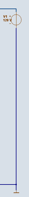
The Voltage Supply = 120 VDC regulated
.
As this amplifier needs a well regulated power supply
at 120 Volt Direct Current, DC
... which is pretty high, except in compare to great Tube / Valves circuits
.. I will use my own precision 120 Volt Discrete Regulator
as this regulator has been posted already twice ( 2 times )
i need not post it here again
my readers will have it in their collection of good discrete regulated power supply schematics,
in the folder named: Lineup Circuits
basically uses one TL431 for good temp stabilty reference
Attachments
Re: The Voltage Supply = 120 VDC regulated
😀 😀
Nice, revealing schematic Lineup.
You really like to keep us all in suspense, don't you?
Cheers,
Glen
lineup said:.
As this amplifier needs a well regulated power supply
at 120 Volt Direct Current, DC
... which is pretty high, except in compare to great Tube / Valves circuits
.. I will use my own precision 120 Volt Discrete Regulator
as this regulator has been posted already twice ( 2 times )
i need not post it here again
my readers will have it in their collection of good discrete regulated power supply schematics,
in the folder named: Lineup Circuits
basically uses one TL431 for good temp stabilty reference
😀 😀
Nice, revealing schematic Lineup.
You really like to keep us all in suspense, don't you?
Cheers,
Glen
You really like to keep us all in suspense, don't you?
In German that's called "Salamitaktik"...
BTW, SoundPerformanceLab, a german based studio gear maker, have discrete op-amps in many of their products, using +-60V rails...
- Klaus
In German that's called "Salamitaktik"...
BTW, SoundPerformanceLab, a german based studio gear maker, have discrete op-amps in many of their products, using +-60V rails...
- Klaus
Interesting discussion here about supply rails. In my discrete op-amp cct (in the 'real men dont use . . . ' thread), I also run with quite high rails - 25 to 35V either side of 0V. At +-15, distortion simulates at about 10ppm. If the rails are taken up to +-30 or 35V, the distorion drops to <1ppm.
Of course, academic issue at these levels, but I have not managedto work out why (BTW, I checked this with f/back - I have not checked the open loop situation).
Hmmm?

Of course, academic issue at these levels, but I have not managedto work out why (BTW, I checked this with f/back - I have not checked the open loop situation).
Hmmm?
Bonsai nice opamp.
Nelson Pass has mentioned the increase of supply voltage to increase performanse in his paper about opamps.
In my view it has not so much to do with the circuit but with the characteristics of the components eg trannies. Using transistors near their optimum operating specs have advantages. Have a look at datasheets eg. in the case of higher voltages look at how capacitances drop at higher voltages. Transistor theory will tell more. As with semiconductors im pretty sure their will be some downfalls too, thinking of noise.
Harmonic distortion content can even be manipulated to a more favourable or better say user or subjective preferred spectrum to a certain degree using diffirent trannies in a certain position or operating at different voltages, thats for those that are more subjective.
Glen could probably tell us more on this.
Higher rail voltages for a given output voltage swing and transistor type gives you less distortion (particularly from the VAS) because the percentage of Vce variation is less.
You get less of Hawksford's "slope distortion".
Cheers,
Glen
You get less of Hawksford's "slope distortion".
Cheers,
Glen
Homemodder - thnks
Glen - yes, this is one of the reasons I used a Hawsford VAS stage. I was hoping to be able to find another 1 or 2 places in the cct where I could take out a few more hundred ppb - but I could not find it despite a good few hours of work.
Glen - yes, this is one of the reasons I used a Hawsford VAS stage. I was hoping to be able to find another 1 or 2 places in the cct where I could take out a few more hundred ppb - but I could not find it despite a good few hours of work.
lineup, the transistors you are planning to use have a maximum rating of 120V, and you are proposing a 120V supply rail.
This doesn't give a lot of safety margin for transients, voltage spikes and the like. Would it be more reliable if you dropped the supply rail to say 110V or even 100V?
This doesn't give a lot of safety margin for transients, voltage spikes and the like. Would it be more reliable if you dropped the supply rail to say 110V or even 100V?
the voltage gain in my prototype
will be
x 20 (= + 26 dB)
this is not in any way effected by if you use Feedback or No Feedback
the figure is all the same, to the decimal:
The output Voltage will be 20 times higher
than input voltage
the final testing is done at output level:
20 Volt RMS (= +- 28.3 Volt peak)
will be
x 20 (= + 26 dB)
this is not in any way effected by if you use Feedback or No Feedback
the figure is all the same, to the decimal:
The output Voltage will be 20 times higher
than input voltage
the final testing is done at output level:
20 Volt RMS (= +- 28.3 Volt peak)
Attachments
2sc2240 - 2sa970
I have used already these bjts in the improved version of my amplifier by substituting MPSA06-MPSA56 with these in small signal stages.
Great improvement. The rise time it is now 1,47ìs instead with MPSAs was 1,9ìs (under the same drive signal and load).
2N5551-2N5401 are real "factory workers". I have used them also in my high power (thus with supply rails up to +/-90Vdc) P.A. type amplifiers with success.
My place was - from the first, when i was registered in diyaudio forum - that the bigger the supply voltage level, the bigger the dynamic range the bigger the headroom, etc, etc, etc......
Lineup, he knows. 😉
Fotios
- Status
- Not open for further replies.
- Home
- Amplifiers
- Solid State
- 120 Volt psu PreAmp - lowest possible G-FeedBack