120V!! supply.
But with 120V!! supply??
I was tried up to +/-35V supply in my discrete preamp.
Lineup has allways big surprises to all of us!
There is a nice ancient Greek word with poor translation in English that suits to Lineup:
ÑÇÎÉÊÅËÅÕÈÏÓ
It is a compound word, composed from the ancient Greek verb: ÑÇÃÍÕÌÉ = I OPEN and the word: ÊÅËÅÕÈÏÓ = WAY.
In Oxford Greek-English dictionary it is translated as: enterprising or forward-looking.
Thus, a better meaning it is: The man who opens new ways.
Fotios
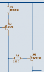
The Voltage amplification, gain stage - VAS
.
In this amplifier, the open loop gain is = closed loop gain.
What this means, is that we have not very much voltage gain, totally.
Closed/Open loop Voltage gain is = 20 (+26dB)
This was chosen for 20 Volt RMS output at 1.0 Volt RMS input signal.
Now, I have 2 stages at hand for making x20.
( The output stage is one buffer gain ~1.0 and put OUTSIDE the fb-loop).
I could go several ways:
and completely unknown to public society I went for Option C).
See today's Attachment 😉
Lineup Audio LAB 😎 MEMBERS Access to our IP = Secrets!
Lineup Audio LAB 😎 MEMBERS Access to our IP = Secrets!
.
In this amplifier, the open loop gain is = closed loop gain.
What this means, is that we have not very much voltage gain, totally.
Closed/Open loop Voltage gain is = 20 (+26dB)
This was chosen for 20 Volt RMS output at 1.0 Volt RMS input signal.
Now, I have 2 stages at hand for making x20.
( The output stage is one buffer gain ~1.0 and put OUTSIDE the fb-loop).
I could go several ways:
For reasons that are Lineup Audio very secret IP, Intellectual Property,A)
> Input stage: x1
> Second stage: x20 ... makes total v-gain x20
B)
> Input stage: x20
> Second stage: x1 ... makes total Gv=20
C)
> Input stage: x2 ... to ... x10
> Output stage: x10 ... to ... x2
all makes total Gv=20
and completely unknown to public society I went for Option C).
See today's Attachment 😉
Lineup Audio LAB 😎 MEMBERS Access to our IP = Secrets!
Lineup Audio LAB 😎 MEMBERS Access to our IP = Secrets!
Attachments
discuss this project in our forum - in Our Audio Community
.
Helloooo!!!!
If you wish to get more into details
of this lineup audio project,
then please
Get your own account (same username as here)
and discuss this project and many other
at our nice new audio forum - for audio designs
Link, if you have not Bookmarked:
http://lineupaudio.freehostia.com/forum
Look for topic
The 120 Volt PreAmp project
... in forum category
Lineup Audio Projects
Lineup 😉
Re: discuss this project in our forum - in Our Audio Community
We choose to be here and you can't tell us where to go.
Just ask. No demands.
no, no and no.lineup said:and discuss this project and many other
at our nice new audio forum - for audio designs
Link, if you have not Bookmarked:
http://lineupaudio.freehostia.com/forum
Look for topic
The 120 Volt PreAmp project
... in forum category
We choose to be here and you can't tell us where to go.
Just ask. No demands.
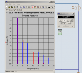
120 Volt PreaAmplifier - Fourier Comparing Analys
.
as Output Buffer is outside feedback loop.
We can call it Local Feedback, including input + second stage.
And the Fourier Results are from the output from third stage.
From the output Buffer Emitter.
Enjoy 😉
Lineup
.
Notice, that this is NOT negative global feed back,.
Comparing FFT Analys
without (blue) vs. with Low Feedback (red)
At 1 .0 Volt RMS input and
20 Volt RMS output ( +- 28.3 Volt Peak )
.
as Output Buffer is outside feedback loop.
We can call it Local Feedback, including input + second stage.
And the Fourier Results are from the output from third stage.
From the output Buffer Emitter.
Enjoy 😉
Lineup
Attachments
Re: Re: discuss this project in our forum - in Our Audio Community
😀 😀 😀
Very good.
This is a reply expressing the traditional Scottish stubbornness (with the good sense of the word) with a spice of humour (at least to me, maybe Andrew does not perceive his saying such and i ask his forgiveness)
Consequently it is not for misunderstanding.
Peace
Fotios
AndrewT said:no, no and no.
We choose to be here and you can't tell us where to go.
Just ask. No demands.
😀 😀 😀
Very good.
This is a reply expressing the traditional Scottish stubbornness (with the good sense of the word) with a spice of humour (at least to me, maybe Andrew does not perceive his saying such and i ask his forgiveness)
Consequently it is not for misunderstanding.
Peace
Fotios
Hi!
I am currently working on the upper rolloff.
Looks like it will be possible to get something like 400 kHz.
With stabilty.
This is not bad for such low feedback
and considerable voltage gain ( Gv=20 ).
Be back with some AC Analysis graphs. Frequency curve + Phase.
😉
Lineup
I am currently working on the upper rolloff.
Looks like it will be possible to get something like 400 kHz.
With stabilty.
This is not bad for such low feedback
and considerable voltage gain ( Gv=20 ).
Be back with some AC Analysis graphs. Frequency curve + Phase.
😉
Lineup
lineup said:Hi!
I am currently working on the upper rolloff.
Looks like it will be possible to get something like 400 kHz.
With stabilty.
This is not bad for such low feedback
and considerable voltage gain ( Gv=20 ).
Be back with some AC Analysis graphs. Frequency curve + Phase.
😉
Lineup
According to several respected diy audio members
an upper bandwidth of like 100-150 kHz is enough.
As they have put it to me, they say they can accept
-0.1 or -0.2 dB at 20000 Hertz.
What do you say 😉
Are you happy, as I am,
if I rolloff this 120 Volt pre amplifier with -0.2 decibel at 20 kHz.
I canput it this way:
This amplifier will at maimum have -0.2 dB at 20 000 Hertz, the upper Audio Band.
Any opinions welcome.
Lineup

Lineup Audio LAB
..... projects, audio, discussions, schematic, pcb, designs, audio
OK
I settle for -3 dB at 100 000 Hz
as no body has got some other opinion on this.
😀 😀 😀
= will be more than I can hear with my ears
We may have to change this roll off frequency
if John Curl comes to visit me 🙄
I settle for -3 dB at 100 000 Hz
as no body has got some other opinion on this.
😀 😀 😀
= will be more than I can hear with my ears
We may have to change this roll off frequency
if John Curl comes to visit me 🙄
CUSTOM 120 Volt preamp - highest possible frequency
😎
Of course,
for any body needing 'maximal high' frequency
I can provide one CUSTOM 120 Volt preamp
with the highest possible F operation & still being stable
🙂
😎
Of course,
for any body needing 'maximal high' frequency
I can provide one CUSTOM 120 Volt preamp
with the highest possible F operation & still being stable
🙂
think maybe I can get as high
as -3 dB at 500 kHz 😎 😎
for Gain = 20 in my 120 Volt low feedback amp
as -3 dB at 500 kHz 😎 😎
for Gain = 20 in my 120 Volt low feedback amp
Can somebody give me a summary of what this is all about? Mr Uppställning has a monologue but about what?
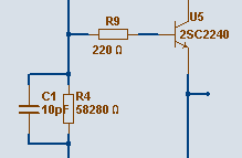
Made some smaller resistance adjustments
... and got even lower distortion + a bit higher bandwidth!
I have now finally changed to 2N5551 output transistor
+ dito CCS for the output buffer.
Lineup 🙂 many diy audio regards
Lineup Electronics Forum - members only
🙂
Lineup Audio BLOG - for everyone
🙂
... and got even lower distortion + a bit higher bandwidth!
I have now finally changed to 2N5551 output transistor
+ dito CCS for the output buffer.
Lineup 🙂 many diy audio regards
Lineup Electronics Forum - members only
🙂
Lineup Audio BLOG - for everyone
🙂
Output Capacitor, Suggestions
.
Any suggestions for the Output Capacitor?
Caps Rating required:
- 100 VOLT minimum, preferably >= 150 VOLT
- at least 4.7 uF, but I would prefer 10 or 22 uF
.. for worst case like 4.7 kOhm LOADS
What say you tube guys 😎
.. you use what for your higher voltage valve outputs?
*Of course I would prefer not to use wet almuinum electrolyts, like Black Gate, BG.
OSCON are too low voltage only.
Remains FILM CAPS - polypropylene / polyester, metalized or not ..
Got one first request for complete schematic!!
so I decided to email my circuit, so far, to him.
He will keep in contact with me while build my amplifier.
As I do not need too many testers, I will not send to more people.
It is quite enough to make one good tasting soup
if we are only a couple cooks in this kitchen 😀
For all that want a full copy of the prototype circuit setup,
I say to them wait some days.
It is too early to publish one amplifier not tested enough.
The basic details aere there and all are already told in my posts above.
If you are not so experienced in diy or do not know my circuit idea,
it is better you wait for a fully tested version.
At least the first built prototype. 😉
Regards
Lineup
so I decided to email my circuit, so far, to him.
He will keep in contact with me while build my amplifier.
As I do not need too many testers, I will not send to more people.
It is quite enough to make one good tasting soup
if we are only a couple cooks in this kitchen 😀
For all that want a full copy of the prototype circuit setup,
I say to them wait some days.
It is too early to publish one amplifier not tested enough.
The basic details aere there and all are already told in my posts above.
If you are not so experienced in diy or do not know my circuit idea,
it is better you wait for a fully tested version.
At least the first built prototype. 😉
Now, I really need some good suggestions for those Output Caps.
See previous post for requirement.
This is one piece we need, for a good working amplifier.
Regards
Lineup
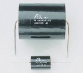
MKP polypropylene capacitor for Audio!!!!!
🙂
Think maybe this will be good ?
As we only need one such per Amplifier Channel, we might as well go for Quality!
6.95 € for 250 Volt, 22 uF. Will be fine 😎
Of course, if you have some other idea .... please tell 😉
🙂
Think maybe this will be good ?
As we only need one such per Amplifier Channel, we might as well go for Quality!
6.95 € for 250 Volt, 22 uF. Will be fine 😎
Of course, if you have some other idea .... please tell 😉
Manufacturer: SCR
Type: MKP
An axial capacitor with metallised poly-propylene dielectric. Polypropylene has several excellent properties such as high stability, low losses, low di-electric absorption and high withstand voltage. The capacitor is self-healing and has low impedance. Particularly suited to audio applications.
Capacitance: 22 µF
Voltage rating: 250 V dc
Tolerance: ±5 %
Attachments
Audio Notes foil capacitors for audio. High End note, certainly
These are probably much too expensive for my amplifier.
But looks interesting.
Judging from this below, the price for 10 uF willl nor be small 😀
The sillver foil comes only 3.3 uF and lower, but has got an attractive PRICE 😎
These are probably much too expensive for my amplifier.
But looks interesting.
Tin Foil Signal Capacitors
CAP-4900 10uF 630 volt
No price yet.
The resulting dry tin foil signal caps have now been on the market for a few years, and the move away from the copper paper in oil prompted us to introduce an oil filling in the tin foil caps as well, since this then makes the processes the same across the board for the tin and the copper foil signal caps, the oil filled tin caps do offer slightly improved sound compared to the dry versions.
Judging from this below, the price for 10 uF willl nor be small 😀
We stock the following standard values in
Copper foil in paper in oil:
CAP-3050 54 mm x 95 mm 10 uF 300 volt £ 114.50
The new copper and silver foil signal caps are available in a range that is specifically targetted at the single-ended triode amplifier market, although most values will also be usable in other types of valve amplification.
I think, however, that apart from the considerable improvement in price, the fact that the new copper foil capacitors are considerably better sounding than anything, including the previous Jensen-made copper signal caps, makes them even better sonic value. The improvement is due to the use of greatly improved materials, better production methods and tighter production tolerances, plus the fact that the new caps are encased in copper instead of aluminium, glass or plastic.
The sillver foil comes only 3.3 uF and lower, but has got an attractive PRICE 😎
*** £ 880 is like € 1300 or expressed in USD $1950 😱 😱 😱 😱CAP-7860 54 mm x 95 mm 3.3 uF 500 volt £ 880.00
An externally hosted image should be here but it was not working when we last tested it.
Making my speakers ready for my 120 Volt Low feedback amplifier
.
I am gettin' ready!
Polishing my best speakers today 😀
To make ready to listen to my super PreAmp
.... wooo haaaa
you never believe what sound will be
what you see is the reflection in one of my speakers top side
you see lamp quite clearly, don't you

Lineup
.
I am gettin' ready!
Polishing my best speakers today 😀
To make ready to listen to my super PreAmp
.... wooo haaaa
you never believe what sound
will bewhat you see is the reflection in one of my speakers top side
you see lamp quite clearly, don't you
Lineup
Attachments
Lineup,
lets have the circuit so we can discuss it. I published my effort - lets see yours.
Come on - we are tired of waiting.
Today!
lets have the circuit so we can discuss it. I published my effort - lets see yours.
Come on - we are tired of waiting.
Today!
- Status
- Not open for further replies.
- Home
- Amplifiers
- Solid State
- 120 Volt psu PreAmp - lowest possible G-FeedBack