Hi, thanks to many of you who helped me design and build my C3G drives 45B monoblocks. I really enjoy them and most surprisingly, I rarely drive them into overload using my 90db efficient speakers (Ilumnia Magisters). The Magisters really excel with the DHT amps. So smooth and natural.
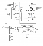
The attached schematic is of the existing monoblocks. I am considering replacing the C3G with a DHT, such as the 10Y. If you have any experience with both the C3G and the 10Y as driver tubes, please share you opinion on the sonic differences. I am curious to learn what sonic changes would accompany the 10Y driver. I am open to DHT alternatives to the 10Y.
Any input would be appreciated.
Pat
Attachments
Last edited by a moderator:
"replacing the C3G with a DHT, such as the 10Y"
No way.
#45 in this schematic requires 2x49V= 98Vpp for full A1 operation.
If you have 2V RMS (5.66Vpp) as input, the VAS stage gain must be -at least- 98/5.66= 17.3 (10/801 has only lesser than 8).
If you want to use single stage DHT tube VAS, only EML 20 or 30 (perhaps ancient 841/VT51) can be considered.

Agree with Euro21 - 10Y doesn't have enough gain. Good driver, of course, and I use it into EL38 in one of my amps.
The first thing I'd do is replace the 45 cathode bypass with a DC Link cap. Kemet or Vishay, you can experiment. I like both. Vishay more pure, Kemet more rich. I used 45uf. I'd also change the last PSU caps to driver and output to DC Link, like 15uF or so.
I don't like solid state in the cathode or anode circuits - has an edge for me I don't like. So I'd use an unbypassed cathode resistor around 200R and figure out an operating point with as low a value cathode resistor as possible while still putting 7mA or more through the driver. To keep the resistor value smaller I use more current and a plate choke with plenty of inductance, like 150H. And a Russian FT-2 teflon 0.2uF coupling cap. I can't comment on Dave Slagle's IT but I know he makes nice stuff. It's totally personal but I've gone from ITs to plate chokes and FT-2 caps these last years.
I have some EC86/6S3P on order as a driver. Haven't received them yet so can't comment but they get good reviews.
Good feedback everyone. I removed the cathode LED and tried several resistors (150, 82, 68, 50, 47) with no bypass cap and find the 68 ohm C3G cathode resistor gives us 156V and 12.5mA, which seems to sound best so far. Much more open, rich and dynamic. Is there a resistor type (film, carbon, etc) that is preferred in the cathode position?
Andy - why do you recommend the last PS cap (currently the Russian PIO 1K 50uF) be changed to a DC Link? Just curious.
Andy - why do you recommend the last PS cap (currently the Russian PIO 1K 50uF) be changed to a DC Link? Just curious.
Andy - why do you recommend the last PS cap (currently the Russian PIO 1K 50uF) be changed to a DC Link? Just curious.
Previously I had good quality polypropylene caps in the PSU and as cathode bypass for the outputs. I replaced these with DC Link caps - Vishay or Kemet - and I got greater clarity and better tone. The upgrade was pretty obvious. So DC Link caps are now my first choice.
Don't know paper in oil caps so can't comment. But I suggest buying some DC Links in 45uF (or similar) and trying them out as cathode bypasses. You should hear a difference - I certainly did. If that works, modify the PSU caps too.
Using Trioda's load line calculator (Triode / Pentode Loadline Simulator v.1.0 (20161216 www.trioda.com)) I am playing around with different Rk values. Which parameters should be optimized? For example: lowest value h2 (Harmonic Distortion) or lowest value Ug or Other?
Agree with Euro21 - 10Y doesn't have enough gain. Good driver, of course, and I use it into EL38 in one of my amps.
The first thing I'd do is replace the 45 cathode bypass with a DC Link cap. Kemet or Vishay, you can experiment. I like both. Vishay more pure, Kemet more rich. I used 45uf. I'd also change the last PSU caps to driver and output to DC Link, like 15uF or so.
I don't like solid state in the cathode or anode circuits - has an edge for me I don't like. So I'd use an unbypassed cathode resistor around 200R and figure out an operating point with as low a value cathode resistor as possible while still putting 7mA or more through the driver. To keep the resistor value smaller I use more current and a plate choke with plenty of inductance, like 150H. And a Russian FT-2 teflon 0.2uF coupling cap. I can't comment on Dave Slagle's IT but I know he makes nice stuff. It's totally personal but I've gone from ITs to plate chokes and FT-2 caps these last years.
I have some EC86/6S3P on order as a driver. Haven't received them yet so can't comment but they get good reviews.
He use no cathode bypass, he use ultrpath with a too high value. Change the ultrapath capacitor to DC link would be a improvement
Is the 530 Ohm cathode resistor of the 45 correct?Hi, thanks to many of you who helped me design and build my C3G drives 45B monoblocks. I really enjoy them and most surprisingly, I rarely drive them into overload using my 90db efficient speakers (Ilumnia Magisters). The Magisters really excel with the DHT amps. So smooth and natural.
The attached schematic is of the existing monoblocks. I am considering replacing the C3G with a DHT, such as the 10Y. If you have any experience with both the C3G and the 10Y as driver tubes, please share you opinion on the sonic differences. I am curious to learn what sonic changes would accompany the 10Y driver. I am open to DHT alternatives to the 10Y.
Any input would be appreciated.
Pat
Cagomat - the 45B circuit is using a 1.5K ohm cathode resistor. this dramatically improved the sound in lieu of the 530 ohm resistor. The circuit was also changed to no longer use ultrapath, as there was too much ripple on B+. So, the 45B bias circuit is using a 1.5K cathode resistor and bypass cap of 50uF.
Cagomat - have you tried Filament Bias on a small driver tube, such as my C3g? I am thinking of trying this to eliminate the cathode cap.
C3g is IDH tube, so filament and cathode not identical, so "filament biasing" not applicable.
If you connect one filament point to cathode and biased tube with (very good DC) filament current via smaller resistor than now, it will be nothing more than the same biasing than now (cathode current via larger resistor).
The problem in the cathode will be the same: DC voltage as bias, but minimal AC impedance.
euro21: thanks for the explanation. I may have to find a new driver tube, as I am trying to find a DHT driver that I can use with filament bias. This will allow for the removal of the cathode bypass cap. I am trying to eliminate caps from the signal path.
My primary challenge is that I need a medium or high mu driver. mu > 30 is my best guess, given that I am driving the amps with a 2V source into a passive attenuator (EMIA Elmaformer). Any thoughts on DHT's that might work with filament bias and also have a mu > 30?
My primary challenge is that I need a medium or high mu driver. mu > 30 is my best guess, given that I am driving the amps with a 2V source into a passive attenuator (EMIA Elmaformer). Any thoughts on DHT's that might work with filament bias and also have a mu > 30?
Every Dht works with filament bias, but most with 50 to 1ü0 Watt reistors. EML 30 is the only one come to my mind. But you must work with an very different IT or plate choke. Bias 10mA and minimum 180Hy IT primary or plate chokeeuro21: thanks for the explanation. I may have to find a new driver tube, as I am trying to find a DHT driver that I can use with filament bias. This will allow for the removal of the cathode bypass cap. I am trying to eliminate caps from the signal path.
My primary challenge is that I need a medium or high mu driver. mu > 30 is my best guess, given that I am driving the amps with a 2V source into a passive attenuator (EMIA Elmaformer). Any thoughts on DHT's that might work with filament bias and also have a mu > 30?
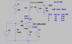
There are many DHT valves that can be used in filament bias in preamps and as drivers in power amps. In the amp that I am building right now I will be using a 10Y in filament bias as a driver. To keep dissipation in the cathode resistor manageable you need a plate voltage below 200 volts, bias at 5 to 7 volts and current at around 15 mA. A 50 W resistor will be OK in this set up. Another good candidate for filament bias is the 4P1L.
In my line amp I use an old battery valve, a Marconi Osram LP2, this class of valve has a low filament current and are very suitable for filament bias use.
I don’t use cathode to ground caps anywhere in my amps. There are several solutions you can use to avoid them. In my phono amp i use D3a valves. They are low bias high current valves that can be run in a configuration similar to filament bias. What you need to do is to set the plate voltage of the valve with a voltage stabiliser valve and connect the cathode of the stabiliser valve to the cathode of the D3a. Then both the D3a current and the stabiliser current will run through the cathode resistor. This will reduce the value of the cathode resistor to half the value needed without the stabiliser, or less. Low enough to make a decoupling cap unnecessary. Unfortunately, this configuration can only be used with a limited number of low bias high current valves. The C3g is not among them.
For the output valve you can use an old Western Electric trick. It can only be done with an interstage transformer (or a pentode driver). What you need to do is to connect a small capacitor from the cathode to the low end of the IT secondary and a large resistor from this point to ground. You can find the calcs in RDH4, but 0,22 uF and 100 KOhms or 0,47uF and 47K Ohms are often suitable.
Good luck with your project!
There are many DHT valves that can be used in filament bias in preamps and as drivers in power amps. In the amp that I am building right now I will be using a 10Y in filament bias as a driver. To keep dissipation in the cathode resistor manageable you need a plate voltage below 200 volts, bias at 5 to 7 volts and current at around 15 mA. A 50 W resistor will be OK in this set up. Another good candidate for filament bias is the 4P1L.
Yes exactly. I use a plate choke and Russian FT-2 teflon cap so I can put 15mA where possible through the driver valve and get a small cathode resistor with no bypass. This doesn't apply in filament bias - it's the filament voltage and current that matters. You need a small bias voltage otherwise the supply voltage is too large. So the 10Y is used with a low bias voltage which it can take, and as high a current as the plate choke is gapped for. For filament bias I like 26 and 10Y. 01A is always attractive sonically, but I've never managed to use it in a useful way with a current of 4mA. Just needs a valve with more current. 46, 47 and 49 sound good, though the demands in filament bias are larger than you want. I keep coming back to 26 and 10Y in the end. One or the other for filament bias. I tried loads of others which eventually I passed over - 4P1L, 2P29L, 1G4, VT-67, 112A, 30, 31, 71, 3a5.... long list. They were all good in a way, some microphonic, but the tone of the 26 shines through in the end, especially on vocals.
Andy, to be fair I got the idea of using the 10Y in filament bias from you.
In the long list of valves you mention in your post there is one Russian valve, the rest are American types. What about European and British valves? There are many valves from this side of the pond that are likely candidates for filament bias. Have you tried any of those? I mentioned the LP2 in my earlier post. This is a very good sounding valve. I’m sure there are many others.
In the long list of valves you mention in your post there is one Russian valve, the rest are American types. What about European and British valves? There are many valves from this side of the pond that are likely candidates for filament bias. Have you tried any of those? I mentioned the LP2 in my earlier post. This is a very good sounding valve. I’m sure there are many others.
Andy, to be fair I got the idea of using the 10Y in filament bias from you. In the long list of valves you mention in your post there is one Russian valve, the rest are American types. What about European and British valves? There are many valves from this side of the pond that are likely candidates for filament bias. Have you tried any of those? I mentioned the LP2 in my earlier post. This is a very good sounding valve. I’m sure there are many others.
Absolutely - European and British DHTs are fine. I don't have any data but they were probably made in fewer numbers than the US valves. Certainly they are pretty rare and expensive these days. Probably in the hands of collectors. I haven't tried any of these.
Andy ban Boli - thanks for the information, very inspiring. Please share your thoughts on the 10Y:
1. what operating points are you using? Boli you said Ua<200Vdc and Ui=15mA and bias 5-7Vdc. Andy?
2. what is your filament bias R value?
3. are you using AC or DC on the filaments?
4. are you using a choke to filter the filament supply? If so, what is the choke specification?
5. Do you find that the type of resistor used in filament supply is impactful on the sound?
This is fun!
- Home
- Amplifiers
- Tubes / Valves
- 10Y (or other DHT) replacing a C3G driver