Just thinking.
You could use a Fontana Bridge. The two differential amps are straight forward to implement in tube form. [physics/0209038] Compensated Current Injection circuit, theory and applicationsm
A cascode is a normal low distortion high output impedance.
It would be possible to use a high Rp tube anode output.. but that’s normally high distortion.
Last edited:
Fontana bridge - Wikipedia
My thinking here is this can be created with op amps (ie low output impedance) for the diff amps - then this also works for cathode following OTLs..
Secondly keeping low impedance means less current noise. Leaving that to the Z network.
I forgot to say - a current feedback into the cathode of the differential tube amp.
Last edited:
just doing the initial maths..
Is = Vin ((Zp+Z1)/(Zp*Z1)
Where Z1=Z2=Z3=Z4 = 10Kohm and Is = 400mA (ie 10W)
0.4 = Vin ((10K+10K)/(10K*10K)) = Vin * 0.002, therefore Vin = 2kV.
I may need another coffee this am.
Is = Vin ((Zp+Z1)/(Zp*Z1)
Where Z1=Z2=Z3=Z4 = 10Kohm and Is = 400mA (ie 10W)
0.4 = Vin ((10K+10K)/(10K*10K)) = Vin * 0.002, therefore Vin = 2kV.
I may need another coffee this am.
thanks for the link to tubecad, indeed what I was looking!
V-to-I Amplifers
The link to the Mills & Hawksford paper on current driven loudspeakers in this tubecad blog does not work any more.
Distortion Reduction in Moving-Coil Loudspeaker Systems Using Current-Drive Technology
*P.G.L.MILLS** AND M.O.J.HAWKSFORD
UniversityofEssex,WivenhoePark,Colchester,Essex,C043SQ,UK
One link which works is halfway down this web page: Amplifiers: Solid State amps verses Valve amps
Last edited:
"Common" totem-pole OTL...
Is possible to achieve high Z with output pentodes with totem pole configuration, if one uses the "gain" configuration in the phase inverter connections.
If one wants to avoid sand at any cost
Is possible to achieve high Z with output pentodes with totem pole configuration, if one uses the "gain" configuration in the phase inverter connections.
If one wants to avoid sand at any cost
Hi Alexandre,
do you happen to have an example for that? I do not know what you mean with "the gain configuration in the phase inverter connections". In OTL there is the Technics and the Futterman, the first has a "cross coupling" from the driver to the output stage, the Futterman has none, therefore attaining higher output impedance 6C33C OTL
best regards,
Erik
The Tube CAD Journal, Totem-Pole Output Stage
Is the "split load gain circuits".
With pentode, will result in a high Z out.
All this article is a must for totem pole stage modes, and PSRR also
Is the "split load gain circuits".
With pentode, will result in a high Z out.
All this article is a must for totem pole stage modes, and PSRR also
Yes, the Futterman is a high-Z one, but since the analysis in tvr site was made with triodes, this result in some moderate/finite out Z.
"Distortion will be higher" affirmation: of course, since the high Z connection excludes the local feedback, the output will have the "full" device distortion
"Distortion will be higher" affirmation: of course, since the high Z connection excludes the local feedback, the output will have the "full" device distortion
I thought a totem pole with Pentodes drives the speaker with a cathode (top tube in the totem pole), and the plate (bottom tube in the totem pole).
But . . .
Cathode impedance is 1/Gm (medium to low)
Plate impedance, rp, is high.
Medium to low impedance, in parallel with high impedance, results in medium to low impedance.
So, the Pentode totem pole amplifier must include current sensed negative feedback to get the output impedance high, Right?
Want OTL with relatively high output impedance, but no current sensed negative feedback?
Use a Totem Pole that has an NPN on the bottom position, and a PNP on the top position, both Collectors drive the speaker (the Collector impedance is much higher than the Emitter impedance). Or do a Totem Pole with N-channel and P-channel MOSFETs, respectively (Drains driving the loudspeaker)
Sorry, that should be a thread in Solid State portion of diyAudio.
Last edited:
In fact, the "Futterman" connection will brings high Z for pentodes, due to manner that the phase inverter is connected, behaving like 2 anode output stages in parallel.
Of course, commercial Futterman amplifiers with pentode out and low Z exists, but is due to global feedback converting gain and gm into low Z (global voltage feedback).
Of course, commercial Futterman amplifiers with pentode out and low Z exists, but is due to global feedback converting gain and gm into low Z (global voltage feedback).
many thanks for all the replies, I think that for the moment I have some concepts and ideas which I can start testin on the bench.
I like the V to I from Tubecad based on 6AS7 with current sensing resistor at the output. Now that I read through the totem pole paper I also understand what all the caps are doing.
In that V to I Broskie also shows some ZEN like amps based on Mosfets. years ago I built there with IRFP240. Meanwhile there are power jfets and I just stumbled upon this one https://www.mouser.ch/datasheet/2/827/DS_UJ3N065080K3S-1530401.pdf Much lower capacitance values than the IRFP, depletion mode (easy biasing and some added current feedback with the r between source and gnd), SOA shows a DC area (so not only for switching applications). Also quite cheap, which I like 🙂 Signal fed to bottom device, upper device as gyrator load.
my own idea is a bit like the F1 (PP) and F2 (SE), but with pentodes as the voltage drivers.
Futterman style amps with pentodes, as shown by DIYBras looks nice to, still all these supplies for G2, which should preferably be regulated, add some complexity. Maybe use some of those JFETs instead of the pentodes 🙂
I have enough inspiration for the upcoming months! Still, test with the resistors first.
Wish you all a nice weekend! Erik
I made a JFET amp, 80V supply and 1.2A standing current, for about 60Vpp output. This is being tested on 8 series connecter 4 ohm drivers. Listening to it, a lot of distortion. Put the scope on it and did a sweep, and saw the clipping between 50 and 60Hz. Why clipping?!?! Then I realized about the resonance frequency, well, at least it has a high output impedance, I can confirm that.
The woofers for the test have a Re of 3,4, and a resonance of 40Hz. The woofers in my line arrays have a Re of 6 ohms, and about 12ohms at Fs, so the ratio is much lower, and maybe I can do something with the equalization, needed anyway. Slowly starting to ask myself if it is worth to pursue this path...
I am aware of the RLC resonsance compensation circuits for tweeters, but if it is worth the effort for these woofers?
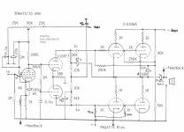
Erik you can also consider this OTL topology for your hybrid amp , where output power tubes have to be replaced with those depletion mode power Jfets (UJ3N065080K3S) , of course many elements and voltages have to be changed to work good with that new solid state OPS , advantage of this configuration is that no DC protection is needed since there`s coupling cap on the output line , and later you can also play with negative/positive feedback network to get desired output impedance , output power can be in range from 30 up to 80 W depending from OPS class of operation , A , A/B .
Best Regards
Best Regards
Attachments
The transconductance idea did not work nice, due to the resonance of the speakers. Logical, afterwards...
I ended up making this amplifier, played it through my line arrays (32x 4R speakers in series) this morning, and it worked.
https://www.diyaudio.com/community/threads/nfb-in-circlotron-more-nfb-higher-thd-why.389662/
I ended up making this amplifier, played it through my line arrays (32x 4R speakers in series) this morning, and it worked.
https://www.diyaudio.com/community/threads/nfb-in-circlotron-more-nfb-higher-thd-why.389662/
- Home
- Amplifiers
- Tubes / Valves
- 10W Current / transconductance bass amplifier for 60 ohms