Byrtt,
Hope you are feeling better with some rest now. Looking forward to hearing sound clips with brick wall xo. Interesting that when top and bottom are integrated there is no ringing - makes send as overall response is smooth because brick wall is hidden in the middle.
Hope you are feeling better with some rest now. Looking forward to hearing sound clips with brick wall xo. Interesting that when top and bottom are integrated there is no ringing - makes send as overall response is smooth because brick wall is hidden in the middle.
xrk, sounding pretty good to me (although I don't know the track). The mids and treble sound clearer.
xrk, sounding pretty good to me (although I don't know the track). The mids and treble sound clearer.
Thanks for the feedback. The sound clip is from "Last Payday" by HCJr
http://youtu.be/2SFV1m66v-Q
This is for the 350Hz BW1 electrical, circa 600Hz acoustic XO frequency setup that had the driver responses flattened with gentle PEQ's prior to applying the XO.
It sounds quite nice. So far I have put on female vocals (Diana Krall sounds really good), live jazz, studio recorded jazz, metal, classical piano concerto, classic rock, pop, male vocals, big band, like a good monitor - all genre's sound equally good.
Right now I am checking for sound stage and imaging and that is doing well too. I can place instruments in a live jazz setting recorded at a night club.
I am not sure if I like this more than the earlier XO I had though. It's close...
I have this strange phase shift above and below the XO that is troubling me. It's like things are in phase above and out of phase below. Flipping polarity made it worse (SR went to hell and it sounds wierd and all phasey with a collapsed stereo image). I may just have too much PEQ going to get the driver responses flat prior to XO. The good old simple way of no PEQ at all and just the XO sounded better phase wise.
Hey X, I reread what you said here and realized I misunderstood you before.
I doubt the phase issues is related to the peq. If you eq each driver to flat then phase for the individual drivers should smooth out and make it easier to align once the crossover is implemented. I think you still just don't have the delay set correctly so the phase is suffering. The 10f is causing the low end phase problems because the slope is so gentle. With BW1 the drivers in the stop band are barely down from the sum so if you have any phase error it'll cause cancellation.
When you flip polarity it's going to make the step go to hell and image to collapse etc. That's normal. What you probably see if you measure with polarity reversed is the sum dipping above the xo and raising below. Probably not too much changes right at the xo, maybe a little dip. This says...phase is still not good! It's interesting that it sounded better phase wise before because it measured worse phase wise. Of course the low end is not going to be particularly accurate in your measurements so maybe I'm basing my opinion on incorrect data and you're hearing what the real truth is.
Anyways, I still contend that second order on the 10f would likely fix a lot of these problems because it would reduce the level of the stop band so it stops screwing with the summed response. It would also cause a little more phase rotation which it sounds like you need. higher order crossovers aren't evil; you'll notice that almost non of the respected designers that post their work online use BW1. Copy the people who know more than you, that's what I do!
Good luck
SATX,
Thanks for the feedback again. I hear what you are saying but most designers of 2-ways are in the multiway forum who are not building a low frequency xo FAST system. I started out with LR4 and it sounds much cleaner - I agree the xo separation was better but I can't get a perfect step response with anything but a 1st order XO. It's a trade off I think because I can really hear the difference the good SR makes on percussion and dynamics of how coherent the sharp leadin edge is, followed by an immediate punch of the woofer.
Can you show me a higher order design XO that has perfect step response?
I am still playing with it but have done a lot of listening over past few days with BW1 and still like what I hear despite your conclusion that the phase below the XO is wrong. If it were wrong - how can the SR be good?
Right now I am using a PEQ flattened response on the woofer that is XO at 350Hz again electrically. This still seems to sound best overall. The place that it makes a huge difference is plucked stand up bass and classical viol. You can hear the individual scratch click caused by the horse hair tugging on the strings of deep notes, followed by the bass they ellicit. Very time accurate and real. Sounds like the players are live.
In a few days I will go to LR2 and listen for a long time again to get a good impression. So far though I am liking what I hear.
Can you show me a higher order design XO that has perfect step response?
Didn't BYRTT already do that? 😉
Anyway, there are a lot of people that don't seem to hear the difference. But I think even if you don't hear it, you can still feel it 🙂.
Last edited:
Byrtt did it with either a BW1 or with FIR in rephase. I might have missed it but I am looking for a IIR filter like LR2 or LR4 or BW2 etc that has good SR without resorting to FIR digital pulse shaping.
Can you show me a higher order design XO that has perfect step response?
I am still playing with it but have done a lot of listening over past few days with BW1 and still like what I hear despite your conclusion that the phase below the XO is wrong. If it were wrong - how can the SR be good?
Can you show me a first order xo that has perfect phase and frequency response?
You may be absolutely correct that the phase is good based on SR. I'm looking at the FR and individual driver response and it says otherwise... but your measurements aren't accurate below the crossover so I may be using invalid data to base my opinion on. Without outdoor measurements SR is probably the best tool to use.
I was just playing in PCD with your drivers and the active filter section trying to understand what is going on. I now see where some of the problems you were have with xo points earlier and the low end phase problems now etc. appear to be coming from.
ANyways, I'm not trying to dispute what you're hearing and I might be totally wrong with my recommendations by basing them on FR data where room reflections are present. At least this is all active and your not building passive xo's for each change!
Hi X,
I just did some sims with your drivers. The Dayton was a little hard to hammer into shape because of baffle step and the wide breakup. I didn't realize that it'd need that much work to hit your slopes. Even at 4th order it doesn't want to cross real low that easily. The 10f took very little eq to look real nice. Just lowering the level some and taming the top end a bit, pretty much what I think you have done.
I know you don't want to use anything higher than 1st order, but in the sims it hits a perfect LR2 targets with a BW1 on the 10f and LR2+peq on the rs225

The Phase is not bad; more of a crossing than good tracking type, but you don't have that phasiness above and/or below the xo.
Here's LR2 on both drivers.

This showed the best overall phase tracking. There not quite there, but at least they're close and parallel.
The first order filters showed the most issues. The sims appeared to predict pretty accurately what you are currently seeing and showing in your measurements, at least in some respects. This is BW1 all around and very little delay; not to bad really except for the shallow slope on the woofer causing issues in the treble.

And the only way that I could get the 10f to show a BW1 slope was to cross it over low and steep, like 6th order at 100Hz. This allows it to keep sensitivity down low, but still protect the driver somewhat. But I couldn't really get this to work well as you can see. The 10f in a small sealed enclosure naturally approximates a BW1 slope at around 350Hz.

I guess if you only listen at low volumes you could not apply a crossover at all on the 10f . That should get you pretty close to BW1 target slopes
Anyways, I hope you can get some benefit out of some of these to understand what the phase etc. is doing.
I just did some sims with your drivers. The Dayton was a little hard to hammer into shape because of baffle step and the wide breakup. I didn't realize that it'd need that much work to hit your slopes. Even at 4th order it doesn't want to cross real low that easily. The 10f took very little eq to look real nice. Just lowering the level some and taming the top end a bit, pretty much what I think you have done.
I know you don't want to use anything higher than 1st order, but in the sims it hits a perfect LR2 targets with a BW1 on the 10f and LR2+peq on the rs225
The Phase is not bad; more of a crossing than good tracking type, but you don't have that phasiness above and/or below the xo.
Here's LR2 on both drivers.
This showed the best overall phase tracking. There not quite there, but at least they're close and parallel.
The first order filters showed the most issues. The sims appeared to predict pretty accurately what you are currently seeing and showing in your measurements, at least in some respects. This is BW1 all around and very little delay; not to bad really except for the shallow slope on the woofer causing issues in the treble.
And the only way that I could get the 10f to show a BW1 slope was to cross it over low and steep, like 6th order at 100Hz. This allows it to keep sensitivity down low, but still protect the driver somewhat. But I couldn't really get this to work well as you can see. The 10f in a small sealed enclosure naturally approximates a BW1 slope at around 350Hz.
I guess if you only listen at low volumes you could not apply a crossover at all on the 10f . That should get you pretty close to BW1 target slopes
Anyways, I hope you can get some benefit out of some of these to understand what the phase etc. is doing.
Byrtt,
I got similar results to you when I applied a huge amount of delay. I think it makes it rotate over and over.

This is delayed by about 2 meters.

I got similar results to you when I applied a huge amount of delay. I think it makes it rotate over and over.
This is delayed by about 2 meters.
SATX,
Thanks for the sims. Where did you get the FRD files for the sims? For the LR2 on RS225 and BW1 on 10F, what were the XO frequencies? I finally took my speaker outside and propped it up on a 6ft ladder with mic 1 m away. The results were eye opening, my bass extends deeper than I thought - the room and floor bounce made if look less than in free space. I have this rise where the XO is on both BW1 and LR2. It was interesting how clean it sounded outdoors without room reflections.
Thanks for the sims. Where did you get the FRD files for the sims? For the LR2 on RS225 and BW1 on 10F, what were the XO frequencies? I finally took my speaker outside and propped it up on a 6ft ladder with mic 1 m away. The results were eye opening, my bass extends deeper than I thought - the room and floor bounce made if look less than in free space. I have this rise where the XO is on both BW1 and LR2. It was interesting how clean it sounded outdoors without room reflections.
Oh good, glad you got it out. How low are you able to see measured outside? You might be able to place the mic a bit closer to get resolution a little bit lower; I think about 30" with an 8" driver. You can get a floor bounce cancellation, that actually could be the cancellation we're seeing between 80-200. I'd just try moving them around a little bit to see if they sound any different.
FRD for the RS225-8 is from parts express and I traced the 10f. I used Response Modeler to include the baffle effects of your box and extract minimum phase from each frd.
XO for BW1/LR2 looks to be at about 350 acoustic. electrical is set at about 250 on the dayton and 300/SS.
If you have a peak at the crossover point then I would just move the crossovers apart a little bit. This is probably because the drivers aren't hitting a textbook slope. Also, I believe that a BW1 is supposed to cause a 3db peak at the xo frequency.

Hi been away a while and at same a little busy dig deeper to the other transient perfect filters done by FIR. Soon will post data those and after that some sound clips. There is reasons it took some extra time about the FIR filters because what i subjective describe and praised from first listening was wrong. Discovered that in the two brick wall FIR filters set at different XO point 150 and 400Hz compared to IRR BW1 350Hz i used the same delay for offsetting acoustic center 0,3mSec and that is wrong. Acoustic center seems as said to change with frequency and the FIR 400Hz needed 0,45mSec and the FIR 150Hz 1,0mSec. The error gave a sound impression of a warm pleasant sound but technical wrong and colouring speaker. Change XO point a bit and offset needs new setting makes one see the neat flexibility running XO in digital domain and especially the BW1 is very sensible to offset because it gives a very low Q peak or dip if wrong set.
satx,
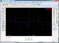
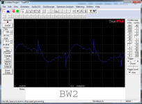
Because as xrk971 i run BW1 in FAST for a 10F i can speak the very difference disappointing sound when changing to another IRR filter being BW2/4 or LR2/4 in i run my XO for these trials in DSP with a click can shift between those filters, and this must be the SR that talks there. Attach pictures a measured 200Hz square wave BW1 BW2 LR2 and LR4 and even BW1 is not a textbook square wave at all steep rising and falling edges is huge difference to the others.
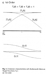
At post 235 (http://www.diyaudio.com/forums/full...-rs225-8-fast-ref-monitor-24.html#post4333589) look in the three plots there should be stuff to understand why having two soft BW1 slopes -3dB at XO point right they sum without any peak or dip if at same acoustic offset is perfect aligned for the XO point frequency. If this is true BW1 don't change frequency response reversing polarity one driver, only thing happening is square waves then looks like BW2 LR2/4 because they now sum their system phase with a 180º turn compared the flat phase when run with same polarity. Attach a old KEF note regarding BW1 the always 90º apart soft slopes that sum flat phase and FR.
satx,
Because as xrk971 i run BW1 in FAST for a 10F i can speak the very difference disappointing sound when changing to another IRR filter being BW2/4 or LR2/4 in i run my XO for these trials in DSP with a click can shift between those filters, and this must be the SR that talks there. Attach pictures a measured 200Hz square wave BW1 BW2 LR2 and LR4 and even BW1 is not a textbook square wave at all steep rising and falling edges is huge difference to the others.
At post 235 (http://www.diyaudio.com/forums/full...-rs225-8-fast-ref-monitor-24.html#post4333589) look in the three plots there should be stuff to understand why having two soft BW1 slopes -3dB at XO point right they sum without any peak or dip if at same acoustic offset is perfect aligned for the XO point frequency. If this is true BW1 don't change frequency response reversing polarity one driver, only thing happening is square waves then looks like BW2 LR2/4 because they now sum their system phase with a 180º turn compared the flat phase when run with same polarity. Attach a old KEF note regarding BW1 the always 90º apart soft slopes that sum flat phase and FR.
Attachments


Last edited:
Hi been away a while and at same a little busy dig deeper to the other transient perfect filters done by FIR. Soon will post data those and after that some sound clips. There is reasons it took some extra time about the FIR filters because what i subjective describe and praised from first listening was wrong. Discovered that in the two brick wall FIR filters set at different XO point 150 and 400Hz compared to IRR BW1 350Hz i used the same delay for offsetting acoustic center 0,3mSec and that is wrong. Acoustic center seems as said to change with frequency and the FIR 400Hz needed 0,45mSec and the FIR 150Hz 1,0mSec. The error gave a sound impression of a warm pleasant sound but technical wrong and colouring speaker. Change XO point a bit and offset needs new setting makes one see the neat flexibility running XO in digital domain and especially the BW1 is very sensible to offset because it gives a very low Q peak or dip if wrong set.
satx,
Because as xrk971 i run BW1 in FAST for a 10F i can speak the very difference disappointing sound when changing to another IRR filter being BW2/4 or LR2/4 in i run my XO for these trials in DSP with a click can shift between those filters, and this must be the SR that talks there. Attach pictures a measured 200Hz square wave BW1 BW2 LR2 and LR4 and even BW1 is not a textbook square wave at all steep rising and falling edges is huge difference to the others.
At post 235 (http://www.diyaudio.com/forums/full...-rs225-8-fast-ref-monitor-24.html#post4333589) look in the three plots there should be stuff to understand why having two soft BW1 slopes -3dB at XO point right they sum without any peak or dip if at same acoustic offset is perfect aligned for the XO point frequency. If this is true BW1 don't change frequency response reversing polarity one driver, only thing happening is square waves then looks like BW2 LR2/4 because they now sum their system phase with a 180º turn compared the flat phase when run with same polarity. Attach a old KEF note regarding BW1 the always 90º apart soft slopes that sum flat phase and FR.
Ah, I had forgotten some of that about BW1 filters. I remembered that they're -3db, but had forgotten that they sum flat and why. As I said, I don't really use first order crossovers so I guess some of my suggestions are incorrect. I do actually prefer lower order slopes to high, but I always shoot for good phase tracking and frequency and power response so mostly stepped baffles and LR2. Tough to do with BW1, but probably really nice when when you get it right.
The last picture you posted, do the dashed lines at the bottom represent the desired phase of a proper BW1
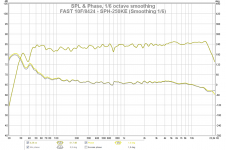
THis is BW1 on the woofer and no crossover on the 10f. The 10f appears to roll off at a perfect BW1 with no crossover in this small sealed enclosure.
Is this something like what kef is showing (look at the phase)?

Is this something like what kef is showing (look at the phase)?
The last picture you posted, do the dashed lines at the bottom represent the desired phase of a proper BW1
Dashed lines show the 90º phase turn the two HP/LP slopes takes, the bottom dashed line is LP being in phase at low end 45º turned at XO point, HP is above with 90º lag at low end 45º at XO point and in phase in high end. The strait line is the linear phase sum for HP/LP slopes isolated and good example showing but there comes a system passband too degrading the strait line at low end and high end for hole system 🙂.
THis is BW1 on the woofer and no crossover on the 10f. The 10f appears to roll off at a perfect BW1 with no crossover in this small sealed enclosure.
Is this something like what kef is showing (look at the phase)?
View attachment 484821
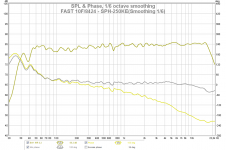
Guess system phase is the light blue in there and seems on the way, below one X did at early stage with miniDSP think that is nice phase.
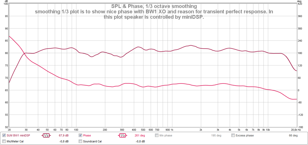
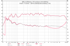
Admit i couldn't just throw a capacitor and inductor and get slopes right at microphone point in space with my setup, but the DSP offer all the tools besides XO to get great results. My 10F sits temporary in a DCR box where it hits 70Hz and this helps of course to get 3 octaves below 350Hz XO point. My phase when running TC9FC looked like the red one below and 10F is the yellow one looking more like a "Danley SH50" phase plot. It should be said the speakers sits in a bookcase against a wall and what that takes of reflections and room modes but actual sound nice and at the microphone point overnice.
Attachments
Guess system phase is the light blue in there and seems on the way, below one X did at early stage with miniDSP think that is nice phase.

Actually the blue is the woffers phase, you can see the breakup at the high end. Orange is the 10f. I included the total phase here, it's the gray line.
Admit i couldn't just throw a capacitor and inductor and get slopes right at microphone point in space with my setup, but the DSP offer all the tools besides XO to get great results. My 10F sits temporary in a DCR box where it hits 70Hz and this helps of course to get 3 octaves below 350Hz XO point. My phase when running TC9FC looked like the red one below and 10F is the yellow one looking more like a "Danley SH50" phase plot. It should be said the speakers sits in a bookcase against a wall and what that takes of reflections and room modes but actual sound nice and at the microphone point overnice.
That looks very nice and the phase is exceptionally flat. Is that system phase or minimum phase?
It seems to me that if X wants to keep BW1 and still have an electrical crossover then he needs to adjust his enclosure so that the 10f has more output down low.
View attachment 484837
Actually the blue is the woffers phase, you can see the breakup at the high end. Orange is the 10f. I included the total phase here, it's the gray line.....
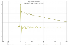
Sorry my eyes didn't catch the grey line that one looks good, member bwaslo said be within +/- 20º phase then reproduce square waves and SR looks good.
.....It seems to me that if X wants to keep BW1 and still have an electrical crossover then he needs to adjust his enclosure so that the 10f has more output down low.
If RS225-8 is so important to get filtered out as you and 5th element suggest then yes else some of the first setups that had acoustic XO around 730Hz had pretty good data measured FR/PHASE/IR/SR and sound clips sounded good especially a 60Mb FLAC he shared 🙂.
.....That looks very nice and the phase is exceptionally flat. Is that system phase or minimum phase?.....
The yellow is system phase as REW measure and grey is minimum phase as is extracted from FR and they ought to be same if system is trimmed for most errors, EQ and filters are all god old IRR ones but done in DSP.
Update: Phase got better i just discover that the AMD-chipset USB port i put my UMIK-1 mic into on that computer was responsible the strange phase. Just changed port to a add in card USB3 and edge on IR/SR got a lot sharper. Therefor forget plot two post 278 it looks like below and add IR/SR plot too. Now measured system phase equal minimum phase pointing to example offset drivers between is optimal at 0,29mSec having those two to meet, same can be seen in group delay plot than then go textbook like.
Attachments
- Home
- Loudspeakers
- Full Range
- 10F/8424 & RS225-8 FAST / WAW Ref Monitor